


2021 Technical Paper #1
CFD Analysis of Pipework Fracture due to Hydraulic Shock in an Ammonia Refrigeration System
Authors:
Chidambaram Narayanan, Principal Engineer AFRY Switzerland AG
Bent Wiencke, Consultant, Chill-On LLC
Lane Loyko, Consultant, PLA Corp.
Abstract
The condensation induced hydraulic shock (CIHS) phenomena is a primary safety concern in low temperature ammonia systems. When transient pressure amplitudes become exceedingly high, pipe rupture can occur. Of particular interest to the ammonia industry is the development of a computational fluid dynamics (CFD) modeling tool that can accurately predict scenarios which can lead to pipe rupture due to formation of a hydraulic shock.
A detailed three-dimensional CFD model capable of predicting the occurrence, the location, and the amplitude of hydraulic shocks was developed (Narayanan et al., 2020) and validated using the experimental study of Martin et al. (2007). The validity and utility of this model for the design and analysis of industrial-scale ammonia refrigeration systems is established in this study by simulating the case of pipework fracture due to hydraulic shock in a frozen food factory (Wiencke, 2008). Simulations were performed with conditions corresponding to soft hot-gas defrost valve (1/2” valve) and main hot-gas defrost valves (2.5” valve) being open. A massive shock of amplitude as high as 4000 psia was predicted for the main hot-gas defrost valve case, whereas no shock was observed for the soft hot-gas defrost valve condition. The study was extended to look at different hot-gas flow rates which showed that a valve size of 2” and smaller may have prevented pipework rupture. The effect of the suction temperature was also analyzed for the same setup to provide additional inputs towards the design of the defrost procedure. The capability and utility of the CFD model to contribute towards design and analysis of industrial refrigeration systems is clearly demonstrated. This study also formed the basis for another research project which will expand on the knowledge gained in this study.
Introduction
This paper presents application of a CFD modelling tool validated for prediction of hydraulic shocks to a well-documented case of pipework fracture due to hydraulic shock in a frozen food factory (Wiencke, 2008). This CFD software was developed and validated (Narayanan et al., 2020) using the experimental study of Martin et al. (2007). The formation of a hydraulic shock is of greatest interest on the low temperature side of the refrigeration system. The CFD modeling tool has been developed and verified against a small number of test cases performed in a laboratory type setting utilizing a capped 6″ schedule 80 pipe, 20’0 long and partially filled with low temperature ammonia liquid at near-saturation conditions. The pipe was meticulously instrumented to monitor the events from the inception of flow to the transition of the flow from stratified to slug flow which trapped gas in the end of the pipe against the cap.
The instruments recorded conditions in the gas void sealed by the slug on one end and the cap on the other end. The instruments monitored these conditions as the gas void collapsed to zero and the slug impacted the end cap, thus creating the high-pressure shock wave and finally the pressure-canceling reflected wave. All these events occur in less than one second in the 20′-long pipe. The data collection equipment was capable of capturing up to 50,000 data inputs per second. Hence the shock wave peak pressure, duration, and shape were well recorded.
The CFD tool therefore captured extremely well-documented, verifiable data, which gives the authors confidence in the ability of the tool to be used in the analysis of other piping structures and initial conditions. This tool is believed to be the first and only CFD tool to incorporate all of the various flow and heat-transfer forces necessary for a predictive hydraulic shock CFD model.
Having validated the model against experimental data, the objective of this study is to demonstrate the applicability of the CFD model to analysis of real accidents in an ammonia refrigeration system, in particular the one analyzed in depth by Wiencke (2008). Parametric study of the effect of hot-gas defrost mass flow rate and temperature was also carried out, thus providing information leading to improved design and a potential update and revision of guidelines for the avoidance of hydraulic shock in ammonia refrigeration systems.
The paper will first present the mathematical model used for the CFD simulations, followed by a short summary of the hydraulic shock accident in a frozen food factory as described by Wiencke (2008). Finally, the results obtained from the CFD simulations and the parametric study will be presented and discussed.
Background
Over the past 30 years, a number of ammonia refrigerant releases have occurred as a result of catastrophic failure of piping, valves and evaporators located in the low temperature part of ammonia systems. Over the past 20 years, careful analysis of these failures has revealed that large pressure surges generated within the ammonia refrigeration system caused many of these failures. The large pressure surges were most likely caused by condensation-induced hydraulic shock (CIHS) in conjunction with the pressure changes that occur when initiating or terminating hot gas defrost. Wiencke (2008) presents a well-documented failure of an 8″ evaporator coil header operating at –50°F in an ammonia system serving a spiral freezer in a frozen food factory.
The U.S. Chemical Safety Board (2015) investigated a hydraulic shock event that occurred on August 23, 2010, at a refrigerated services facility in Theodore, Alabama. The consequence of this hydraulic shock event was catastrophic failure of a 12-inch suction pipe located on the roof. Subsequently, 32,100 pounds of anhydrous ammonia was released into the atmosphere. One onsite worker and 152 offsite workers were exposed to the ammonia. Of the 153 workers exposed, a total of 32 workers were admitted to the hospital and four were placed in intensive care. This incident, as reported, had many commonalities with the incident described by Wiencke (2008).
Loyko (1989 and 1992) reports several failures in the piping of ammonia refrigeration plants: a 1.25-inch endplate blown off a pan coil header, a 4-inch weld cap blown off a wet suction return line, and a 16-inch end plate blown off a wet suction line. IIAR (1992) published Bulletin 116 which presented recommended piping practices with the aim of preventing the occurrence of some hydraulic shock events. From Bulletin 116, the term “soft hot gas defrost system” originated where the hot gas control valves, timers, and appropriate sequencing for closing and opening control valves and fan motors was described. Shelton and Jacobi (1997) reviewed the literature concerning the phenomenon of condensation-induced hydraulic shocks. Hydraulic shock events not resulting in failure are reported by Glennon and Cole (1998) where events similar to “water hammer” were investigated. Also, both Loyko (1992) and Glennon and Cole (1998) recommend system piping designs and operating conditions to minimize the occurrence of hydraulic shocks based on their analysis of the system operating conditions that led to the pressure spikes. The literature cited above collectively makes two conclusions: 1.) Failures occur primarily in evaporators and two-phase suction piping, and 2.) Failures occur primarily upon initiation or termination of hot gas defrost.
Condensation Induced Hydraulic Shock (CIHS)
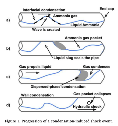
CIHS (or condensation induced water hammer) occurs when there is accumulated or stratified liquid flowing in the piping, over which or behind which vapor at high velocity is introduced during a start-up transient. The typical sequence of events leading to a hydraulic shock is shown in Figure 1. For a horizontal pipe partially filled with liquid, there is a shear force of the gas acting on the gas-liquid interface. The interface forms waves which eventually grow to develop slugs covering the full crosssection of the pipe.
Further flow of upstream vapor pushes the slug toward a pipe end closure or similar endpoint such as a valve. As the trapped vapor becomes pressurized, it condenses onto the oncoming slug and on the pipe walls. Thus, the slug does not experience any resistance to its motion and eventually collides with the end closure resulting in a hydraulic shock due to rapid collapse/condensation of the trapped gas. IIAR guidelines note that such a phenomenon can happen at the beginning of hot gas defrost. Liquid slugs arise in the hot gas piping to coils that are mostly filled with liquid or at the termination of defrost as a result of slugs formed in the two phase suction lines flowing into sections of the piping that are closed and have no exit.
The shock pressures that are generated are commonly higher than the maximum allowable working pressure of the low side of a refrigeration piping system and/ or the setting of the pressure relief safety valves installed and designed to protect the system. It can now be confirmed through CFD modelling that these high-peakpressure, short-duration, hydraulic shock pressure waves can exceed the strength of common low temperature ammonia refrigeration system piping. In addition, the transient pressure amplitude exists only for a short duration and is localized. If a pressure relief device were to be installed close to the location of the shock event, the short duration of the pressure rise would be too fast for the pressure relief valve to respond.
Mathematical and Numerical Modelling
The mathematical model used in this study is the compressible non-equilibrium multiphase mixture model (Saurel and Lemetayer, 2001) where each phase has separate equation of state (EoS) such that the phases can be superheated or subcooled. The detailed mathematical formulation is presented in Labois and Narayanan (2017) and further details regarding its ability to model liquid slug formation, vapor propulsion, and condensation models is available in Narayanan et al. (2020). Turbulence is modelled using the mixture Reynolds averaged NavierStokes (RANS) approach.
Two-phase Homogeneous Mixture Model
For multiphase flow problems, two different numerical techniques are available. The Interface Tracking Method is exclusively used for two-phase flows where the interface between the two fluids is sharp, and its evolution is to be tracked. The second technique is the mixture model where the two-phases can be separated or get mixed depending on the flow conditions, and a clear interface between the vapor and liquid phases is not always available. In the compressible two-phase homogeneous mixture model, presented in Labois and Narayanan (2017), the conservation equations of mass is solved for each phase, whereas the momentum, pressure, and temperature are solved only for the mixture.
Condensation Modelling
Condensation controls two critical aspects of the CIHS problem. On one hand, vapor flow into a closed system results in a pressure rise and reduction in the velocity of the vapor. This hinders the formation of a liquid slug. At the same time, even if a slug is formed, the process of hydraulic-shock creation depends on the propulsion of the liquid slug due to condensation of the trapped gas pocked downstream of the slug leading to its eventual collapse. Therefore, sufficiently accurate modelling of condensation is necessary to predict the formation of a hydraulic shock.
Phase-change phenomena (boiling and condensation) can be broadly categorized as thermally limited or inertial phase change. Thermally limited phase change occurs when the temperature departs from the saturation condition while the system pressure remains constant (typically when heat is introduced or removed from a system). Within the thermally limited category, condensation can occur via several different mechanisms or modes, such as interfacial condensation, dispersed-phase condensation, or wall condensation. Inertial phase change occurs when the pressure changes rapidly but the temperature varies less. This is referred to as cavitation or flashing. Cavitation or flashing models are required for situations of turning liquid flows or for cases of depressurization.
In a study simulating the hot-gas defrost process (Narayanan et al., 2020), the dispersed-phase, thermally limited condensation model was found to be sufficient. However, depending on the pipework configuration, cavitation modelling could be necessary to successfully consider movement of a liquid slug through pipe bends and elbows. The cavitation model also comes into play during the final stages of the formation of hydraulic shock due to the rapid collapse of the trapped gas/bubble. Detailed description of both condensation models used is available in Narayanan (2020). In the simulations presented here, both the thermally limited and cavitation models were used.
Numerical Modelling
The model is implemented into TransAT© software which is a finite-volume CFD solver specializing in the modelling of multiphase flows. The convective terms in the momentum and phasic continuity equations are discretized using the second-order HLPA scheme (Zhu, 1991), whereas in the pressure equation the first-order upwind scheme is employed. The diffusion terms are discretized by second-order central differencing in the momentum and temperature equations. The pressure equation is solved using the SIMPLEC pressure correction method of van Doormaal and Raithby (1984). First-order backward Euler time stepping is used for the unsteady problems presented here.
The compressibility of the two-phase system is modeled using pressure-based methods developed by Labois and Narayanan (2017). The local densities for each phase are calculated from the equation of state, ρk = ρk (T,p), where k denotes the phase. Both the phasic mass conservation equations are solved because, in general, the continuous phase can change in different regions of the flow. The volume fraction constraint Σαk = 1, is maintained by consistent discretization (Labois & Narayanan, 2017) and by subtracting the mixture continuity equation from each of the discrete phasic mass conservation equations.
Material and Transport Properties
In this multiphase flow model, each phase has a separate EoS and phases can be in metastable states, i.e., superheated liquid and subcooled vapor. The fluid progresses towards equilibrium through phase-change source terms. The liquid density is estimated using the modified Tait EoS, whereas the vapor density is estimated using the Ideal gas EoS. Apart from the density, the simulation of the CIHS problem requires the specification of the latent heat of vaporization/condensation, the saturation curve, and the estimation of the speed of sound for both phases (available through the EoS). All the data used in this study has been compared with data available in the NIST Database for Ammonia (see Narayanan et al. 2020 for more details).
Pipework Fracture Case Study (Wiencke 2008)
In June 2007, a deflagration occurred at a frozen food factory. The incident investigation identified a ruptured coil located in a spiral freezer as the source of the ammonia leak. Within a 20-minute time frame, the ammonia concentration in the room surrounding the freezer enclosure increased to a flammable level and subsequently a deflagration occurred. The arcing found in a wire inside a drinking fountain was the likely ignition source. The freezer and its associated refrigeration infrastructure were in operation for more than 10 years and underwent 3 Process Hazard Analyses. The incident investigation concluded that a hydraulic shock caused by a vapor propelled liquid slug generated enough of a transient pressure spike to cause coil rupture. A detailed analysis of the control valve group and liquid transfer vessel design and system dynamics, in conjunction with a metallurgic fracture analysis, was used to develop a mathematical model to describe and reconstruct the mechanism of this incident. The results are quite startling and support the fact that a seemingly insignificant system upset has the potential of leading to a catastrophic event.
Figure 2 shows a schematic of the liquid transfer vessel, and controls valve and pipework system connected to the spiral freezer coils.
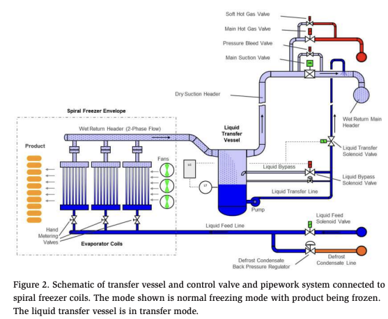
Prior to the accident, the liquid level controller of the liquid transfer vessel failed, allowing the liquid transfer vessel to be entirely filled with liquid. The liquid transfer vessel was not equipped with a separate mechanical level switch. The incident investigation concluded that the evaporator coils were nearly full of liquid. It was determined that the wet return header between the liquid transfer vessel and the evaporator coils was empty of liquid. The control sequence simply relied on a timer to ensure that the “soft” hot gas step would build up sufficient pressure to safely open the main hot gas valve. It was also concluded that the hot gas introduced by the smaller soft hot gas valve had no effect, i.e., pressure was not building up. Figure 3 illustrates a simplified schematic of the condition the system was in just prior to the catastrophic failure.
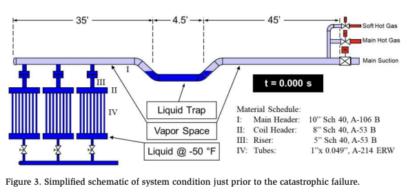
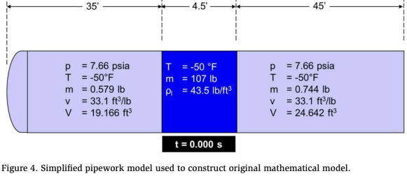
Figure 4 is a simplified pipework model that was used to construct the original mathematical model. Elbows are not accounted for here. Shown in the center is the liquid slug generated by the trap formed by the transfer vessel. To the left of the slug is the vapor space situated right above the liquid-filled coils. To the right of the slug is the vapor space the hot gas was introduced into. The steady state conditions are shown at t=0s
Based on the mathematical model and the analysis conducted, it took the liquid slug 0.855 sec to travel from its initial resting position to the end of the wet return header, where it came to rest upon impact with the endcap. The resulting shock wave propagated through the liquid downward into the evaporator coil. Figure 5 shows the position of the liquid slug at time of rupture and also the locations where the fractures occurred. The arrows indicate the shock wave propagation.
Figure 6 shows the location of the fractures and pictures of the fractured components. To substantiate and validate the conclusions from the forensic analysis and the results from the mathematical model, the components that were potentially exposed to the high-pressure amplitudes from the hydraulic shock were analyzed. Metallurgical and mechanical testing were conducted, as was finite element and fracture mechanics analysis. Figure 7 is a summary of the results.
It is notable that the main header exhibits a significantly higher burst pressure than the header manifolds associated with the coils. Furthermore, it was concluded that the first coil from the right was unaffected by the hydraulic shock. Presumably, this coil including its vertical header connecting it to the main header was entirely filled with liquid. As shown in Figure 5, when the impact occurred, the vertical header connecting the coil to the main header was no longer exposed to the liquid slug, but to hot gas. The original mathematical model and its derivation is explained in detail in the original paper by Wiencke (2008).
In summary, the equipment that enabled the hydraulic shock in the incident was the previously mentioned valve group and a failed level controller in combination with the liquid transfer vessel serving the low temperature freezer and a failed liquid level controller. This valve group was designed without any additional safeguards, consistent with most valve group designs in the industry during that time period. In fact, a certain type of fast acting main suction valve is still commonly being used. This type of valve opens instantaneously upon power failure and opens without any positive feedback that the differential pressure has been lowered to a safe level. Many of the older valve stations do not have a soft hot gas valve, allowing a gradual pressure build-up before the main hot gas valve opens.
Most new valve stations having a soft hot gas valve do not use any positive feedback that the pressure has reached a safe level before the main hot gas valve is opened.
Thus, if a high liquid level develops in the evaporator coil (e.g., due to a valve or control failure), there are no safety interlocks and the defrost sequence is often not aborted. Most valve groups designed in the past and still being designed today do not include safeguards that protect the system in case of a system upset or failing equipment such as sticking solenoid valves, burned out solenoid valve coils, failing level controllers, oil fouling, etc. The level controller associated with the liquid level transfer vessel was not provided with any safety interlocks. Consequently, any failure of the liquid level controller resulting in excessive liquid buildup in the liquid transfer vessel (complete flooding) did not initiate an alarm nor prevent hot gas from being introduced.
CFD Simulation of Case Study
The pipework of the frozen food plant was modeled in detail, as shown in Figure 8. The pipe has a diameter of 10 in., and the pipework includes several 90° bends. The transfer vessel has not been included in the CFD model however a layer of liquid is considered to be trapped at this location. The question being asked is whether a certain flow rate of hot gas will result in the formation of a liquid slug followed by a hydraulic shock; and if so, what would be the amplitude of such a shock.
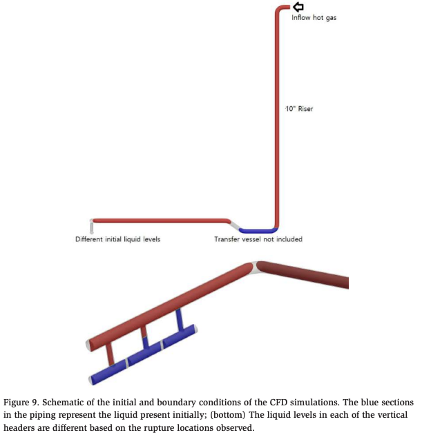
The simulation setup consists of the pipe geometry shown in Figure 8, which is meshed with a resolution of 20 mm across the diameter of the pipe. Figure 9 shows the schematic of the computational domain and the mesh. The mesh size along the pipe was between 20-80 mm. As seen in the sketch, a layer of liquid is initialized at the lowest section of the pipework (above the transfer vessel).
Due to the liquid plug already filling up the cross-section, it must be noted that the process of slug formation as described in the context of Figure 1 is not necessary in this scenario. The injected gas will directly push the liquid plug along the pipework. In the three vertical pipes connecting to the coil header, liquid is initialized to different levels in an attempts to capture the rupture locations. The initial temperature was set to –50°F with the pressure set to the saturation pressure at that temperature. The time step during the simulation varied between 0.1 ms and 0.4 ms. For the base case, the hot-gas flow rate was set to 5.4 lb./s at a temperature of 41°F.
For the thermally-limited phase change model, the dispersed-phase diameter was set to 300 microns, and for the cavitation model the nucleation density was set to 25 x 104 and the minimum nucleate radius was set to 0.001 (Yuan et al., 2001). As mentioned earlier, the cavitation model is essential to allow the liquid slug to move through the pipe bends at high velocities.
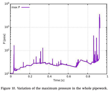
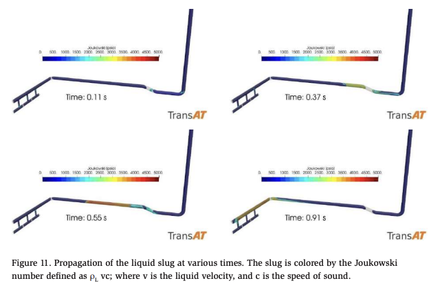
Variation of the maximum pressure in the computational domain is presented in Figure 10. It is observed that after 0.9 seconds, a large shock with an amplitude of almost 4000 psia is predicted. The sequence of images presented in Figure 11 shows the development of the liquid slug and its movement towards the closed end of the pipework. The liquid slug is formed and appears to be fully mobilized towards the end cap by around 0.5 seconds. After 0.91 seconds, a strong hydraulic shock is predicted at the downstream vertical pipe connecting the coil header. The slug travels through the pipework with a velocity of approximately 21 m/s (69 ft/s or 50 mph).
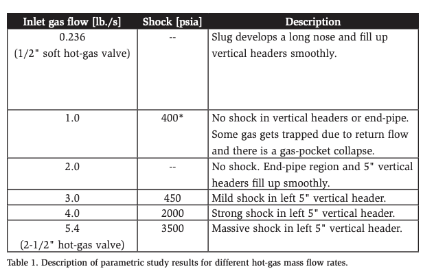
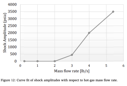
A set of simulations were performed with reducing hot-gas mass flow rates and the observations are summarized in Table 1. As the flow rate reduces, the shock amplitude reduces rapidly to the extent that at 4 lb./s, the shock amplitude is well below a value that could cause pipe rupture. A curve fit of the variation of the shock amplitude with respect to the hot-gas flow rate is shown in Figure 12, which shows a highly non-linear increase in the shock amplitude with hot-gas flow rate.
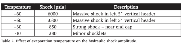
The effect of the evaporation temperature (initial liquid temperature) was studied for the highest mass flow rate of 5.4 lb./s and the results are summarized in Table 2. The shock amplitude decreases with an increase in the temperature to the extent that at temperatures higher than –30°F, the shock amplitudes are quite low.
In summary, the simulations show that time taken for the formation of strong hydraulic shock was approximately 0.9 secs after opening of the 2.5″ main hot gas solenoid valve in this example. We could demonstrate that defrost gas flow from the ½” soft hot gas valve of 0.2 lb/sec will not produce a strong shock. Flow rates of around 5.4 lb/sec can give rise to shocks of substantial amplitudes of 9,000+ psia. The shock amplitudes reduce non-linearly with decrease in the hot-gas flow rate such that it goes below 4,000-5,000 psia (safety limit) for flow rates below 4 lb/s for this example. It was also shown that at evaporation temperatures higher than –30°F, the shock amplitudes are significantly below the safety limit.
Conclusions
The compressible, non-equilibrium, multiphase model validated with the dataset of Martin et al. (2007) was applied to a real catastrophic event scenario where pipework fracture was observed. The results of this CFD analysis align closely with the forensic analysis of the actual failure. The model provided the precise timing of the shock along with the magnitude of the shock pressures associated with the rupture. There now exists a CFD tool that is capable to assist in the forensic analysis of existing ammonia refrigeration piping systems to examine hydraulic shock events.
In a parametric analysis, the operating temperature of the system and the hot gas flow rates were altered. The results show that above –20°F, the transient pressure amplitudes were reduced to values that most probably would have posed no risk to the system. The transient pressure amplitudes are strongly dependent on the amount of hot gas mass flow introduced and its rate. The cubic polynomial order for the shock amplitudes with respect to flow rates is much higher than one would expect. A valve size one size smaller would have generated much smaller pressure amplitudes, and consequently, the catastrophic failure of the pipe work system may have been prevented.
In the analyzed system there was a piping geometry that created a liquid trap in the suction piping at the beginning of the hot gas flow. The shock would not have occurred if the liquid plug in the trap was not present. In the analyzed case, the evaporator coils were inadequately pumped out at the beginning of the hot gas flow due to a low product heat load in the freezer immediately preceding the onset of the hot gas cycle and inadequate timer setting. The low heat load condition allowed the coils to brine and fill with liquid, making an effective pump-out impossible prior to the onset of hot gas flow.
This study supports and reiterates the following recommendations by Wiencke (2008) and by the U.S. Chemical Safety Board (2015), which are summarized here and not all inclusive:
- Avoid design geometries such as “liquid traps” that can cause the formation of a vapor-propelled liquid slug.
- Select appropriate materials (e.g., low temperature steel and stainless steel) for piping systems and evaporators that may potentially be subjected to hydraulic shocks.
- Incorporate safeguards in the overall control valve group design:
- When the defrost sequence is interrupted, such as manual intervention or power outage, the system must default into a fail-safe state.
- Evaporator coils should be void of nearly all liquid prior to introducing hot gas. Consequently, this necessitates inclusion of a pump-out, push-out, or boil-off sequence as part of the defrost sequence. Safeguards interlocked with the control sequence should be provided to ensure that nearly all liquid has been removed from the coil.
- The control sequence should not rely on timers to build up hot gas pressure to a safe level. Instead, pressure transducers or pressure switches should be used to provide positive feedback that a safe pressure has been reached before opening the main hot gas valve or introducing high mass flow rates of hot gas. Alternately, advanced dual position hot gas valves with integrated safety features can be used.
- Upon termination of hot gas defrost, the evaporator coils including piping and control valve group must be safely depressurized prior to opening the main hot suction valve. Timers should not be relied upon, but instead pressure transducers or pressure switches should be interlocked with the control sequence. Alternately, advanced two step valves with built in safety features can be used.
The ammonia refrigeration industry would strongly benefit from a CFD modelling tool to help analyze generic valve group designs in low temperature applications. The emphasis of such a study could be to evaluate generic piping designs in the two locations where hydraulic shock occurs most frequently: (1) the hot gas piping from the valve group to the evaporator header, and (2) the wet suction piping from the evaporator. This tool could also be used to study the impact of different valves such as standard fast-acting solenoid valves or slow-acting motorized valves.
References
Glennon C, Cole RC. 1998, “Case Study of Hydraulic Shock Events in an Ammonia Refrigeration System.” IIAR 20th Annual Convention, Colorado Springs, Colorado, USA.
International Institute of Ammonia Refrigeration (IIAR). 1992. “Bulletin 116. Guidelines for: Avoiding Component Failure in Industrial Refrigeration Systems Caused by Abnormal Pressure or Shock.” IIAR, Alexandria, VA.
Labois M Narayanan C. 2017. “Non-conservative pressure-based compressible formulation for multiphase flows with heat and mass transfer,” International Journal of Multiphase Flow: 96, 24-33.
Loyko LL. 1989. Technical Paper 125, “Hydraulic Shock in Ammonia Systems.” IIAR 11th Annual Convention, Austin, TX, USA. Loyko LL. 1992. Technical Paper 165, “Condensation Induced Hydraulic Shock.” IIAR 14th Annual Convention, Miami, FL, USA.
Martin C ., Brown R, Brown J. 2007. “Condensation-Induced Hydraulic Shock, Final Report.” Tech. Rep. ASHRAE 970–RP.
Narayanan C. 2020. “Numerical simulation of flashing using a pressure-based compressible multiphase approach and a thermodynamic cavitation model.” International Journal of Multiphase Flow: 103; 511.
Narayanan C, Thomas S, Lakehal D. 2020. “CFD Study of Hydraulic Shock in TwoPhase Anhydrous Ammonia.” ASHRAE Transactions, Volume 126, Part 2.
Saurel R, Lemetayer O. 2001. “A multiphase model for compressible flows with interfaces, shocks, detonation waves and cavitation.” Journal of Fluid Mechanics: 431; 239.
Shelton JC, Jacobi AM. 1997. “A Fundamental Study of Refrigerant Line Transients: Part 1: Description of the Problem and Survey of Relevant Literature.” ASHRAE Transactions. Vol. 103, Part 1.
Shelton JC, Jacobi AM. 1997. “A Fundamental Study of Refrigerant Line Transients: Part 2: Pressure Excursion Estimates and Initiation Mechanisms,” ASHRAE Transactions, Vol. 103, Part 2.
U.S. Chemical Safety Board (CSB). 2015. “Key lessons for preventing hydraulic shock in ammonia refrigeration systems.” https://www.csb.gov/file. aspx?DocumentId=5933.
van Doormaal J, Raithby GD. 1984. “Enhancements of the simple method for predicting incompressible fluid flows.” Num. Heat Transfer: 7, 147-63.
Wiencke B. 2008. “A Case Study of Pipework Fracture due to Hydraulic Shock in an Ammonia System.” IIAR Technical Paper, 30th Annual Meeting, Colorado Springs, CO, USA.
Yuan W, Sauer J, Schnerr GH. 2001. “Modeling and computation of unsteady cavitation flows in injection nozzles.” Mécanique & Industries: 2(5); 383-94.
Zhu J. 1999. “A low-diffusive and oscillation-free convection scheme.” International Journal for Numerical Methods in Biomedical Engineering: 7(3); 225-32.
Acknowledgements
The authors gratefully acknowledge the support received from Advanced Modelling & Simulation group at AFRY Switzerland.
