2021 Technical Paper #12
Designing Industrial Refrigeration Systems for Full Vacuum – Considerations
Author:
Martin L. Timm, P.E., CSP, Managing Member, Centigrade Services LLC
Abstract
Considerations around modes of test and operation that place ammonia refrigeration systems in a vacuum are discussed. A literature review of IIAR publications and general industry recommendations regarding design of pressure vessels and systems for evacuation and operation is presented. Results are presented for ASME B&PVC calculations for a range of typical pressure vessels constructed from A516 carbon steel showing that full vacuum should not be applied to vessels that exceed a specified length to diameter ratio (L/D), unless the vessel nameplate indicates it has been designed for full vacuum.
Introduction
ANSI/IIAR 2 American National Standard for Safe Design of Closed-Circuit Ammonia Refrigeration Systems and other industry codes and standards have required that refrigeration equipment be designed for vacuum. Sometimes the level of vacuum specified is “full vacuum” and other times as 29 inches mercury (29 inHg, 737 mmHg). Readers may wonder why a vacuum this “deep” is specified, given that systems normally operate at low-side “pressure” corresponding to a mild vacuum no lower than 10.4 psia (8.75 inHg, 222 mmHg), corresponding to a saturation temperature of –40°F (–40°C). The IIAR 2 standard does not provide a rationale. Readers may also wonder what equipment design features are needed to satisfy the “full vacuum” requirement and specifically whether vessels specified for a maximum allowable working pressure (MAWP) of 250 or 300 PSIG are “automatically” suitable for full vacuum. This paper reviews evacuation as a method to remove moisture and non-condensables during commissioning, prior to charging a system with ammonia, and other operations that can cause a vacuum in a system during operation. This paper also addresses the relationship between the MAWP and the minimum allowable working pressure, and pressure vessel authority requirements regarding the marking of nameplates of vessels suitable for full vacuum.
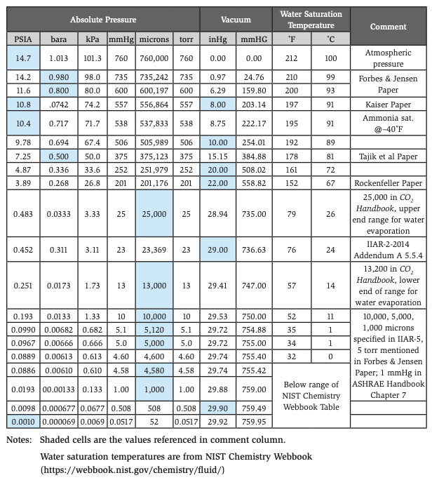
A variety of units of measure are used in industry for vacuum. A conversion chart for the convenience of the reader is included in the Appendix. The chart includes the saturation temperature (boiling temperature) of water at the indicated levels of vacuum.
Literature review
Current IIAR Publications
IIAR Bulletin 108 Guidelines for: Water Contamination in Ammonia Refrigeration Systems discusses the negative impact of water as a contaminant of ammonia in refrigeration systems, and states that a common source of water is inadequate evacuation prior to charging of the system [1]. An acceptable level of vacuum to target for proper moisture removal is not mentioned.
IIAR’s CO2 Handbook discusses evacuation in Chapter 16 [2]. The opening paragraph in that chapter downplays the importance of evacuation for ammonia systems because water is absorbed “with minimal adverse effects,” and air is quickly expelled by the system purger. These statements are somewhat at odds with the guidance in IIAR Bulletin 108. Chapter 16 goes on to say that CO2 is extremely sensitive to water in the system and recommends a first evacuation to 5,120 microns (29.72 inHg) , corresponding to water boiling at 35°F (5.4°C), repeated if necessary, after breaking the vacuum with dry nitrogen, with a final pull down to 500 microns (29.9 inHg), followed by a 24-hr hold during which pressure does not rise.
ANSI/IIAR 1-2017 American National Standard for Definitions and Terminology Used in IIAR Standards does not contain any definitions for “evacuation,” “vacuum,” or word combinations thereof [3].
IIAR’s current design standard, ANSI/IIAR 2-2014, Addendum A, American National Standard for Safe Design of Closed-Circuit Ammonia Refrigeration Systems, and the previous version, IIAR 2-2014, both include sections 5.5.4 that state “Refrigeration equipment shall be designed for a vacuum of 29.0 in. (737 mm) of mercury.” [4][5], but these standards do not provide any explanation or rationale in the normative or informative text. A 29-in. Hg vacuum corresponds to 23,370 microns. The next earlier version of IIAR 2, IIAR 2-2008 Addendum B, included text in section 15.1.7.2 requiring system evacuation to 10 in. Hg (250 mm Hg) after completion of leak testing and prior to charging with ammonia, but had no corresponding design requirement in the pressure vessel chapter [6]. This was also true of all earlier versions back to 1978.
The ANSI/IIAR installation standard, IIAR 4-2015 American National Standard for Installation of Closed-Circuit Ammonia Refrigeration Systems, includes section 13.1.4, which addresses leak testing, evacuation, and dehydration, only to the extent that it references Appendix C in ANSI/IIAR 5-2013 American National Standard for Startup of Closed-Circuit Ammonia Refrigeration Systems and requires compliance [7].
The latest edition of the IIAR 5 startup standard, IIAR 5-2019, addresses evacuation in section 5.5, “Pressure Tests, Leak Tests, and Evacuation” [8]. It states that such tests be done on all pressure-envelope portions of the system. It further states that the system be evacuated first to a pressure of 10,000 microns (29.53 inHg), and after doing some checks, than to a pressure of 5,000 microns (29.72 inHg), or 1,000 microns (29.88 inHg) if using compressed air for the pressure test. The 5,000 microns is presumably if using dry nitrogen or other dry inert gas for the prior pressure test. Note that the recommended vacuum levels of 10,000, 5,000, and 1,000 microns (29.53, 29.72, and 29.88 inHg) are all a deeper vacuum than the 29 inHg (23,400 microns) that IIAR 2-2014, Appendix B, specifies as the design pressure vessel vacuum level. Deeper vacuum (lower absolute pressure) is a more severe design case than less deep vacuum, but the difference in required wall thickness may be quite small.
The evacuation method in IIAR 5-2019 is further elaborated in non-mandatory Appendix C. The appendix further recommends that once the target vacuum is reached, the vacuum pump be shut off, and the system allowed to stand for one hour, with an acceptable result if pressure rises no more than 1,000 microns (.04 inHg) during that time.
IIAR-5-2019 cautions that pressure switches be valved off or disconnected during evacuation since some switches may not have vacuum protection. IIAR 5 states seal volumes and other components requiring an oil charge for sealing should be charged and rotated by hand to assure distribution on the seal faces. IIAR-5 refers the reader to manufacturer’s recommendations to determine if there are any special considerations to be followed during evacuation. Appendix D in IIAR 5-2019 notes that deep evacuation may not be possible in all cases when tie-ins are being done, but all parties involved should agree on appropriate procedures.
ANSI/IIAR 6-2019 American National Standard for Inspecting, Testing, and Maintenance of Closed-Circuit Ammonia Refrigeration Systems recommends that systems operating in a vacuum test for contamination of the ammonia every three years [9]. It also refers to dehydration in accordance with IIAR 5. Appendix C in IIAR 6 goes into details regarding consequences of water contamination but offers no further guidance on the target vacuum level during evacuation. IIAR 6 observes that a vacuum can be created when draining oil into a water-filled container using improper procedures, and this can result in water being drawn into and contaminating the system.
ANSI/IIAR 7-2019 American National Standard for Developing Operating Procedures for Closed-Circuit Ammonia Refrigeration Systems makes no mention of vacuum or evacuation, except for one statement that a possible emergency response to a leaking evaporator is to lower the evaporator suction pressure into a vacuum [10].
The IIAR Ammonia Data Book mentions the importance of avoiding contamination of ammonia with air, because it can contribute to stress corrosion cracking (SCC) [11]. It emphasizes use of evacuation procedures prior to charging as described in IIAR Bulletin 108. It also recommends use of purging procedures after startup.
IIAR Conference Papers
Hansen states that failure to evacuate a system prior to charging new systems or additions can be a source of non-condensables [12].
Landry notes that water can be sucked into drums of compressor oil during nighttime cooling of the drum if water is sitting on top of the bung [13].
Rockenfeller, et al describe a device that can be used for removing ammonia from refrigerating systems down to a vacuum of 22 inHg (201,200 microns) [14].
Kaiser mentions that for food freezing applications, cold ammonia liquid may be circulated at conditions as cold as –40°F, at a vacuum of 8 inHg [15]. This pressure and temperature corresponds to –40°C at 556,900 microns.
Forbes and Jensen describe conversion of several facilities from R-22/R-502 systems to ammonia, during which the residual halocarbon refrigerant was removed by evacuation [16]. In one case, they describe three steps of evacuation to a final vacuum of 5 torr (5,000 microns, 29.72 inHg). The first two steps used a high capacity single stage 18.5 kW vacuum pump to reach 0.8 to 0.98 bara (600,200 to 735,200 microns, 6.29 to 0.97 inHg), and the last step used a dual stage vacuum pump. Between evacuations, the vacuum was broken with dry nitrogen. They describe another case in which only one step of evacuation was performed, which proved highly problematic when chemical reactions between halocarbon and ammonia refrigerant resulted in severe plugging of strainers with powdery solids.
Riley discusses pipe stress and flexibility analysis, and his Table 5 showing allowable external pressure (vacuum) for A106A and A106B pipe in sizes from ½” to 30″ and wall schedules is consistent with IIAR recommendations [17]. Table 5 shows that all listed combinations of diameter, wall thickness, and metallurgy are acceptable for full vacuum if no corrosion has occurred. The table shows that ½” and ¾” SCH 80 pipe and 30″ standard wall pipe, are not suitable for full vacuum if 80 mils of corrosion has occurred (4 mil/yr for 20 years). Riley’s calculations assumed that all piping was at a temperature at or above –20°F (evacuation condition), not at a lower operating temperature.
Breun, et al commented that circa 1980, system commissioning was not always rigorous or systematic, with charging of the system occurring after a quick pressurization with air for leak checking, followed by evacuation [18].
Mattes described water/lithium bromide (LiBr) absorption refrigeration plants as operating in the deep vacuum range, in contrast with ammonia absorption plants that operate at a higher pressure, but was not specific regarding how “deep” the water/LiBr vacuum is [19] refrigeration is generated by using compression-type refrigeration plants that are driven by electric power. However, other processes like absorption type refrigeration plants may also be applied. Unlike the compression refrigeration process, in an absorption type refrigeration plant the refrigerant vapor is not compressed mechanically but absorbed in the absorber by a suitable liquid (absorbent, multi-component mixture. Mattes also mentions use of an ejector for purging non-condensables during operation of the water/LiBr system.
Thomson describes the dangers of mixing high-pressure ammonia gas with cold liquid, and describes several incidents of condensation-induced shock, some of which resulted in loss of containment and significant damage and disruption to the facility. He describes how contact of cold liquid with the hot gas results in condensation of the vapor and local formation of a deep vacuum, which can cause liquid to rush in to fill the vacuum, developing high velocities that can damage equipment when a liquid slug is suddenly stopped or redirected by valves, elbows, tees, etc. [20].
Strömblad describes troubleshooting various systems with plate heat exchangers [21]. He describes one system in which performance was compromised by waxy deposits in a plate heat exchanger due to interaction of oil, moisture, and ammonia. The moisture in the system was blamed on an overly large vacuum pump used to evacuate the system, which drew down the system pressure so quickly during evacuation, that the residual water froze in place rather than being removed by evaporation. He also describes how an oscillating pressure-vacuum condition can be created in water and brine circuits that can be damaging to plate heat exchangers if the design does not account for the pressure shifting.
Danilewicz, et al state that ASHRAE 15-2004 specifies that all equipment should be designed for a 29 inHg vacuum (23,370 microns, 29.00 inHg) [22]. He also mentions use of purgers to remove non-condensables from systems operating in a vacuum, and refers to IIAR Bulletin No 108 regarding effects of water contamination.
Jordan describes the use of pump-out systems to facilitate removal of ammonia from portions of a system undergoing maintenance or expansion, and describes how some such systems can pull the equipment being pumped out into a partial vacuum [23]. He cautions that it is not advisable to break a deep vacuum with air prior to opening the system, as air can form an explosive mixture if mixed with oil and ammonia. He recommends breaking the vacuum with dry nitrogen to raise the pressure to just above 0 psig (1.013 bara).
Other Sources
Nielsen discusses the importance of avoiding water contamination in ammonia refrigeration systems, and the practice of pulling sufficient vacuum and flushing with hot dry nitrogen before charging a system [24].
Brundrett describes three principal scenarios which result in the pressure being higher outside of a vessel vs. inside the vessel [25] and once jackets or other sources of pressure are added the difficulty increases. The external pressure rating depends upon more variables and the failure mechanism is more difficult to understand.
This article is only an introduction, but it also covers many of the areas of external pressure that often need to be explained. Common mistakes made with external pressure calculations are listed. Sample vessel calculations are included throughout this article based on a vessel 48″ diameter x 96″ long with a Flanged and Dished (F&D):
- From a vacuum inside a vessel and atmospheric pressure outside
- From a pressure outside a vessel greater than atmospheric (typically from some types of jacket or a surrounding vessel)
- From a combination of the first two – vacuum inside + pressure greater than atmospheric outside.
Brundett also examines variations of designing for external pressure related to jackets, half-pipe coils, conical sections, etc.
The ASHRAE Refrigeration Handbook has several chapters that touch on the subject of evacuating air and moisture from refrigeration systems [26].
- Chapter 2, “Ammonia Refrigeration Systems,” mentions that incomplete evacuation can leave air or moisture in the system, which later affects performance.
- Chapter 7, “Control of Moisture and Other Contaminants in Refrigerant Systems,” is focused on halocarbon refrigerants, but does discuss sources and effects of moisture and recommends evacuating systems to 1 mm Hg before charging with refrigerant.
- Chapter 8, “Equipment and System Dehydrating, Charging, and Testing,” is informative on general concepts, but is focused mostly on systems or equipment that are dried or evacuated in a factory, with little information on field-erected systems in general or ammonia refrigeration systems in particular.
Berman reviews complexities of dealing with water removal from processing equipment used in semiconductor manufacturing and other high vacuum applications. He discusses key parameters such as surface preparation, surface history, outgassing rate from the surface vs. vapor removal rate, etc. [27].
Eskridge, et al discuss vacuum rating of pressure vessels, and the common practice of rerating for vacuum or deeper vacuum when application requirements change over the vessel lifetime. They point out that the rerating can be done easily and quickly with current pressure vessel design software. For many vessels, there is little or no cost if the vacuum rating is done at the time of design [28].
The ASME Boiler and Pressure Vessel Code defines full vacuum to be the condition where the internal absolute pressure is 0 psia (0 kPa) and external absolute pressure is 15 psia (103 kPa) [29].
Sloley and Shepherd re-state an old rule of thumb, which is that vessels designed for MAWP of 50 PSIG or higher are also suitable for full vacuum with little or no added cost. However, they then go on to provide an example of a 4 ft OD x 12 ft-long pressure vessel that required a shell thickness corresponding to 116 PSIG before it could be stamped for full vacuum [30]. They also explain that not designing a vessel for vacuum can add costs associated with examining vacuum deviations during process hazard analysis, and providing safeguards against a vacuum occurring.
Tajik, et al describe considerations in the specification of pressure vessels in the chemical processing industry [31]. They discuss the scenario whereby a vacuum can be formed in a pressure vessel if it is cleaned by “steaming out,” and is subsequently cooled without providing a flow path for air to enter and keep a vacuum from forming as the steam condenses. They describe specifying some vessels for “full vacuum,” which they describe as 0.0 bara, while saving costs by specifying other vessels for “partial vacuum” of 0.5 bara.
ASME Code Calculations
Every ASME pressure vessel nameplate shows the maximum allowable working pressure at a coincident temperature. The nameplate may or may not show if the vessel is also rated for full or partial vacuum, perhaps by a designation such as 150 PSIG/FV. When the full vacuum or partial vacuum rating is missing from the nameplate, then the question arises as to what vacuum level might be suitable for that vessel. The following discussion provides a starting point for evaluation when vacuum information is missing from the nameplate, but the reader is urged to do vessel-specific calculations before applying this information in the field.
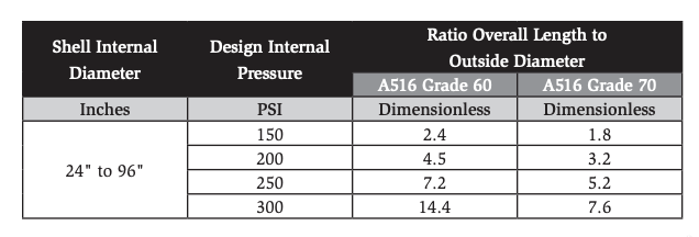
The author performed ASME Boiler and Pressure Vessel Code [32] calculations per Section VIII, Division 1, using both a spreadsheet for parametric analysis and a commercial software program [33] to spot check the spreadsheet calculations. Required thicknesses for internal pressure were calculated per UG-27, and for external pressure per UG-28. Results of calculations done for pressure vessels constructed from carbon steel A516 Grades 60 and 70, varying in inside diameter from 24″ to 96″, are shown in Table 1.
An examination of Table 1 shows that A516 Grade 70 pressure vessels designed to current IIAR recommendations for low-side MAWP of 250 PSIG and high-side MAWPs of 250 and 300 PSIG are likely suitable for full vacuum, unless their overall length to diameter ratios (L/D) exceed 5.0, which would be unusual for industrial refrigeration applications. Economical vessel design typically results in pressure vessels with an L/D of less than 5.0, unless constrained by packaging or site layout considerations.
Assumptions:
- Steel manufactured using “small grain practice”
- No post-weld heat treatment
- Welded seam efficiency 100% (Full radiography)
- Simple Shell with Cylinder + 2 elliptical heads
- No designed-in corrosion allowance
- No loss of wall thickness due to corrosion
- No allowance for loads other than internal or external pressure
Table 1. Maximum Overall Length to OD Ratio for Full Vacuum
It can also be seen from Table 1 that vessels constructed from A516 grade 60 or 70, but designed at MAWPs of 150 or 200 PSI, may not be suitable for full vacuum if the L/D ratio exceeds the values shown in the table. These would typically be low-side vessels at least six years old, since in 2014 IIAR 2 mandated a higher low-side design pressure, raising the minimum 150 PSIG to a minimum 250 PSIG [5].
It is interesting to note that when a vessel is designed for internal pressure only, the use of A516 Grade 60 material results in thicker walls than when the higher-tensile-strength A516 Grade 70 is used. This greater wall thickness at a given internal design pressure makes the Grade 60 vessel more resistant to vacuum collapse/buckling than a vessel constructed from Grade 70 or other higher-tensile-strength material.
It should also be noted that vessels often have wall thickness greater than the minimum required for the MAWP stamped on the nameplate, as they are fabricated from plate and formed heads coming from the mill at standard thicknesses that may slightly exceed what is required. In these cases, a careful analysis based on the manufacturing drawings may justify operating the vessel at a deeper vacuum. The analyst may be tempted to apply similar logic to corrosion allowance, but that urge should be resisted, as reduction in wall thickness due to corrosion reduces both the allowable internal pressure and the allowable external pressure (vacuum).
The comments above are focused on vessels in “new” condition. Vessels with corrosion or other defects accumulated over time, when evaluated for continued fitness-for-service, may prove to have a reduction in both allowable internal pressure and allowable external pressure (vacuum).
ASME Nameplates
A recent ASME interpretation for B&PVC Section VIII, Division 2, states that marking external design pressure on a vessel nameplate is not required if designing for external pressure (vacuum) was not specified as a design condition by the user or his designated agent. But if designing for and stamping the nameplate with external pressure was required, then the external pressure rating must appear in the manufacturer’s data reports as well. Furthermore, the interpretation states that when designed for 15 psi external pressure, the shorthand “FV” for “full vacuum” may be used on the nameplate [34].
Removal of Free Water by Evacuation Prior to Charging
A primary purpose of evacuation is the removal of air from the system prior to charging with ammonia. A secondary but important purpose is the removal of water from the system. It can be argued that evacuation to 22 inHg (201,200 microns) is effective at removing both air and water vapor from the system. At that level of vacuum, any remaining residual air can be removed by purging from the high side after startup. Residual water vapor may contribute a few parts per million (PPM) to the water concentration in the ammonia after charging, but this is acceptable as refrigeration grade ammonia is required to contain some water at the PPM level to inhibit stress corrosion cracking.
Note that the paragraph above refers to water vapor. However, liquid water may exist in the system as a residue of hydrostatic testing of pressure vessels or piping, or it may enter during construction if piping or vessels are left open to the elements. If there is liquid water in the system, a deeper vacuum may be required to both detect it and remove it.
Liquid water detection is achieved by a “hold test,” as described in Appendix C of IIAR 5-2019: Once the target vacuum is reached, the vacuum pump is shut off, and the system is allowed to stand for one hour, with an acceptable result if pressure rises no more than 1,000 microns (.04 inHg) during that time. The target of no more than a 1,000 micron pressure rise over one hour is somewhat arbitrary; the owner and contractor may agree on different “success criteria.” If the vacuum won’t “hold” (i.e., pressure rises quickly) then there is either liquid water in the system being evacuated or there is an air leak. Since it is undesirable to have either air leaks or liquid water in the system, a leak test failure should trigger further efforts to repair leaks and/or remove liquid water from the system before it is charged with ammonia.
For the hold test to be meaningful in detection of liquid water, the temperature of the vessels or piping must be above 32°F where the liquid water is most likely located, otherwise the water will be in the form of ice, whose sublimation occurs very slowly, unlike the boiling of water which sublimates much more easily. Similarly, at a given temperature of the piping and vessels being tested, the vacuum level should be low enough to cause any free liquid water to boil.
Example: Assume the ambient temperature around a system of vessels and piping is 79°F (26°C), and the uninsulated pipe and vessels are at that temperature. According to the table in the appendix of this article, the saturation pressure of water at that temperature is 28.94 inHg (25,000 microns).
Case 1: If the evacuation target is for a less deep vacuum, say 20 inHg (252,000 microns), the free liquid water would not be expected to boil. The water would be in a subcooled condition and, in the absence of air leaks, the system would likely pass a “hold test,” even though there is still liquid water present.
Case 2: If the vacuum is deeper than the saturation pressure, say 29.53 inHg (10,000 microns), the saturation temperature of water is 52°F. The metal walls at 79°F would be warmer than the boiling temperature of water, so any liquid water that was present would boil, and the system would likely fail a hold test. If the system passes the “hold test”, then the owner and contractor can be confident that the system is “dry” and does not contain liquid water.
It is interesting to note that while a target vacuum of 29.53 inHg (10,000 microns) was used in this example for Case 2, a less deep vacuum could also be effective for detecting water in the situation described. For example, evacuating to say 29.13 inHg (20,000 microns), corresponding to a water boiling temperature of 72°F, would still provide a 7°F temperature difference between the warm metal walls and colder boiling water, making the hold test sensitive to the presence of liquid water.
Liquid water removal from a system prior to charging with ammonia can be accomplished by holding the system at a deep enough vacuum to boil water at the ambient temperature conditions for sufficient time to transfer heat to and remove the water. The owner and contractor will know the time has been sufficient when the system is capable of passing the hold test.
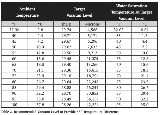
Holding a new system at a deep vacuum to remove liquid water and conducting the hold test may not be required, or even justified when the owner and contractor have complete confidence that the as-built system is free of liquid water. There is a cost associated with the extra time and effort to achieve deep vacuum and to pass a hold test, but when an ammonia charge is contaminated with unacceptably high water content, the impact on efficiency and cost of removing the water can be high. If there is any doubt about the “dryness” or tightness (absence of air leaks) of the as-built system, a deep evacuation, followed by a hold test, should be considered. Table 2 shows the vacuum required across a range of ambient temperatures to provide a 5°F temperature difference (driving force) to boil out water in a system containing liquid water.
Conclusions and Recommendations
A516 Grade 60 or A516 Grade 70 carbon steel vessels with all of the following characteristics are likely suitable for full vacuum:
- Outside diameter size range of 24″ to 96″
- Design MAWP of 250 or 300 PSIG
- Have not suffered corrosion or other defect during use
- Overall length not greater than five times the outside diameter
Vessels with a design MAWP of 150 PSIG or 200 PSIG are more likely to be unsuitable for full vacuum, with a “shorter” allowed ratio of overall length to outside diameter. If the allowable vacuum is not noted on the vessel ASME nameplate, Table 1 can be used as a starting point for evaluation, followed by detailed analysis prior to field use of the information.
Differences of opinion exist within the ammonia refrigeration industry as to the necessary and prudent level of evacuation that should be performed prior to charging a system with ammonia. The evacuation level specified in IIAR 5-2019 is much deeper than that previously specified in historical versions of IIAR 2. Language in the IIAR CO2 Handbook seems to question the need for the deeper evacuation of ammonia systems.
There are small differences in the ASME definition of full vacuum (15 PSI external pressure), the IIAR 2-2014 Addendum A requirement that pressure vessels be designed for a vacuum of 29 inHg, and the IIAR 5-2019 requirement that systems be evacuated (prior to charging with ammonia) to 29.53 inHg or deeper vacuum.
The vacuum target of 29.53 inHg (10,000 microns) in IIAR 5-2019 may be overly conservative, as shown in the example in this paper. A less restrictive, but still effective, approach for detection and removal of liquid water would be to stipulate that the vacuum level attained during evacuation be deep enough that the boiling temperature of water at that vacuum level is at least 5°F (2.8°C) below the ambient temperature where the system is located.
Recommendations:
- IIAR technical committees should consider reviewing the requirement for the vacuum level that must be attained and held during evacuation prior to charging with ammonia and make the vessel design requirement in future versions of IIAR 2 consistent with the specified evacuation vacuum level required in IIAR 5.
- Evacuation levels less deep than 29.53 inHg (10,000 microns) should be considered when:
- The equipment being tested is at a temperature above 57°F (13.9°C), or
- The goal is to remove air and water vapor and to find leaks, but not to remove liquid water
- Owners and contractors should consider including details about evacuation procedures and hold-test success criteria in contract documents so that expectations can be communicated, and resources planned and budgeted appropriately.
- To eliminate confusion and maintain consistency with the ASME B&PVC definition of full vacuum, the IIAR Standards Committee should consider a change to IIAR 2 requiring that new ammonia pressure vessels be designed for an external pressure of 15 PSI.
- The IIAR Standards committee should consider specifying that ASME pressure vessel nameplate information include the allowable vacuum level, either FV for full vacuum or an actual value if not FV.
References
[1] (IIAR), “IIAR Bulletin 108 Water Contamination in Ammonia Refrigeration Systems.” International Institute of Ammonia Refrigeration, Washington, D.C. [2] (IIAR), “Chapter 16 Evacuation,” in CO2 Handbook, Alexandria, VA: International Institute of Ammonia Refrigeration, 2019. [3] (IIAR), “IIAR 1-2017 Definitions and Terminology Used in IIAR Standards.” Alexandria, VA, 2017. [4] (IIAR), “IIAR 2-2014 Addendum A, Safe Design of Closed-Circuit Ammonia Refrigeration Systems.” Alexandria, VA, 2019. [5] (IIAR), “IIAR 2-2014 Safe Design of Closed-Circuit Ammonia Refrigeration Systems.” Alexandria, VA, 2014. [6] (IIAR), “IIAR 2-2008 Addendum B Safe Design of Closed-Circuit Ammonia Refrigeration Systems.” International Institute of Ammonia Refrigeration, Alexandria, VA, 2012. [7] (IIAR), “IIAR 4-2015 Installation of Closed-Circuit Ammonia Refrigeration Systems.” International Institue of Ammonia Refrigeration, Alexandria, VA, 2015. [8] (IIAR), “IIAR 5-2019 Startup of Closed-Circuit Ammonia Refrigeration Systems.” International Institute of Ammonia Refrigeration, Alexandria, VA, 2019. [9] (IIAR), “IIAR 6-2019 Standard for Inspection, Testing, and Maintenance of Closed-Circuit Ammonia Refrigeration Systems.” International Institute of Ammonia Refrigeration, Alexandria, VA, 2019. [10] (IIAR), “IIAR 7‐2019 Developing Operating Procedures for Closed-Circuit Ammonia Refrigeration Systems.” International Institute of Ammonia Refrigeration, Alexandria, VA, pp. 1–55, 2019.
[11] (IIAR), Ammonia Data Book. Alexandria, VA: International Institute of Ammonia Refrigeration. [12] C. C. Hansen III, “Purging and Purgers for Ammonia Refrigeration Systems,” in IIAR Proceedings, 1982. [13] J. F. Landry, “The Effects of Contaminants On Compressor Oils in Ammonia Systems,” in IIAR Proceedings, 1987. [14] U. Rockenfeller, P. Sarkisian, and L. Kirol, “A Device for the Efficient Storage and Recycling of Ammonia During Pump-Out and Emergency Situations,” in IIAR Proceedings, 1993. [15] G. D. Kaiser, “Identification and Modeling of Worst-Case Scenarios for Ammonia Refrigeration Systems,” in IIAR Proceedings, 1996, vol. 2422, no. 202. [16] M. Forbes and S. S. Jensen, “Conversion from R22/R502 to R717: Practical Experiences From Four Industrial Plants,” in IIAR Proceedings, 1997, no. 202. [17] T. Riley, “Pipe Stress or Flexibility Analysis in Refrigeration Piping,” in IIAR Proceedings, 2000. [18] L. Breun, J. Andrie, and S. Gladis, “Compressor Start-up Or System Start-up,” in IIAR Proceedings, 2001. [19] H. E. Mattes, “NH2/H20 Absorption Refrigeration Plant for Large Capacities,” in IIAR Proceedings, 2001. [20] R. B. Thomson, “Overpressurized System Components, Hydrostatic Expansion, and Hydraulic Shock,” in IIAR Proceedings, 2002. [21] M. A. T. Strömblad, “Troubleshooting Ammonia Refrigeration Systems with Plate Heat Exchangers,” in IIAR Proceedings, 2007. [22] P. Danilewicz and P. Orlando, “Refrigeration Piping : A Simplified Guide to a Modern Approach,” in IIAR Proceedings, 2005. [23] P. R. Jordan and K. Hinds, “The Joy of Ammonia Pump-Out Systems,” in IIAR Proceedings, 2006. [24] P. S. Nielsen, “Effects of Water Contamination in Ammonia Plants,” in IIAR Proceedings, 1998, vol. 1110. [25] L. Brundrett, “External Pressure,” 2012. [Online]. Available: pveng.com/home/ asme-code-design/external-pressure-methods. [Accessed: 24-Dec-2019]. [26] Anon, ASHRAE Refrigeration Handbook. Atlanta, GA: ASHRAE, 2018. [27] A. Berman, “Water Vapor In Vacuum Systems,” Vacuum, vol. 47, no. 4, pp. 327–332, 1996. [28] C. Eskridge, M. James, and S. Zoller, “Avoid Common Mistakes with Vessels – Avoid Costly Design Mistakes,” Chemical Processing, pp. 1–21, 2014. [29] (ASME), “Mandatory Appendix 3 Definitions,” in ASME Boiler and Pressure Vessel Code, New Yrok, NY, 2019. [30] A. Sloley and S. Shepherd, “Full vacuum rating isn’t an empty benefit,” Chemical Processing, 2008. [31] N. Tajik et al., “Static Equipment : A Look Inside the ‘How and Why’ of Specification,” Oil Gas Facilities, 2019. [Online]. Available: https://pubs.spe. org/en/ogf/ogf-article-detail/?art=4919. [Accessed: 24-Dec-2019]. [32] Anon, “Boiler and Pressure Vessel Code, Section VIII, Division 1.” ASME, New York, NY, 2017. [33] “Compress Version 7.” Codeware, Sarasota, Florida. [34] “ASME Interpretation VIII-2-04-08 – Required Marking for External Pressure.” 2005.Appendix. Vacuum Conversions and Corresponding Saturation Temperature of Water.