2026 Tech Paper: CO2 Heat Pumps: Main Differences from Refrigeration Systems and Real-World Applications
Author:
Ivan Rangelov, Industrial Heat Pumps Business Development Manager, Danfoss (6000 Kolding, Denmark)
Mazyar Karampour, Sustainable Applications Expert, Danfoss (111 64 Stockholm, Sweden)
Abstract
CO2 has gained significant momentum in the North American refrigeration and heat pump industry in recent years, particularly in transcritical applications. Even though CO2 refrigeration technology is already fully mature in terms of component availability, control strategies, and best practices, CO2-based heat pumps are still a relatively recent development.
This paper focuses on explaining the fundamental similarities and differences between a refrigeration system and a heat pump using CO2 as a refrigerant. Although the architectures and main components of these systems are generally the same in principle, there are important practical differences, most notably in control logic. In particular, there are several parameters that inform the control logic of a CO2 refrigeration system and a heat pump. The first part of this paper focuses on describing this key difference as well as several other minor differences.
The second part of the paper presents two case studies demonstrating the successful operation of a CO2 heat pump that provides for the full thermal demands of their building. These application examples include:
- An air–water or water–water CO2 heat pump–chiller for space heating, domestic hot water heating, and space cooling in commercial buildings in Europe
- An air–water or water–water CO2 heat pump system for heating and cooling in a building HVAC system in the USA
Introduction
CO2 refrigeration technology has undergone significant development over the past few decades. Following its reinvention in the 1990s, the new millennium has been characterized by rapid growth in both subcritical (cascade) and transcritical CO2 refrigeration systems. Subcritical CO2 systems gained popularity in industrial refrigeration (IRF) applications around 20–25 years ago, primarily as the first stage in cascade configurations. In contrast, transcritical systems became widely adopted in food retail applications (such as supermarkets) around this time.
The adoption of this technology in Europe over the past decade has been remarkable. As of December 2023, approximately 68,500 supermarkets and 3,300 industrial facilities operated with CO2 refrigeration technology, representing nearly 72,000 transcritical CO2 systems across the continent. In comparison, there were only 29,000 systems in operation in 2020 and 40,000 in 2021, reflecting an average annual growth rate of 30–40%. In North America, more than 3,400 food retail stores and industrial facilities had adopted transcritical CO2 systems by the end of 2023, representing an 80% increase compared to the previous year (Atmosphere, 2023).
Over the past decade, transcritical CO2 systems have increased significantly in size, driven by advancements in compressor and valve technology. While early commercial racks typically offered cooling capacities of 100–150 kW (340–510 kBTU/hr), modern systems can now reach capacities of 2–2.5 MW (~6,800–8,500 kBTU/hr). This scalability has allowed CO2 systems to be employed in large-scale industrial applications for both refrigeration and heat pump (HP) operations.
Although transcritical CO2 technology has not yet achieved the same market penetration in North America as in Europe, recent installation trends have been used to forecast rapid growth in this area. Several factors are driving this expansion:
- Regulatory initiatives: The US AIM Act mandates an 85% phase-down of hydrofluorocarbons (HFCs) by 2036, thereby accelerating the transition to nextgeneration, environmentally friendly HVACR and HP technologies (EPA, 2024).
- Environmental and safety benefits: CO2 is a natural refrigerant with an ozone depletion potential (ODP) of 0 and a global warming potential (GWP) of 1. In addition, CO2 is non-toxic and non-flammable, making it suitable for use in densely populated areas where other refrigerants may present safety concerns. Finally, CO2 is classified as an A1 refrigerant according to the ASHRAE standard 34 (ANSI/ASHRAE, 2019).
- Unique thermodynamic characteristics: Under certain conditions, CO2 can deliver exceptional efficiency, making it an attractive solution for a variety of applications.
This paper focuses on CO2 HP systems with the aim of sharing practical experience from European industrial applications, discussing critical factors influencing CO2 performance in HP systems, proposing application mappings, and benchmarking the coefficient of performance (COP) of CO2 HPs against selected alternative technologies.
CO2 as Refrigerant
CO2 is unique among refrigerants due to its distinct thermophysical and heat transfer properties. One of its most defining characteristics is its low critical temperature of 31°C, which enables operation in the supercritical region, where temperature and pressure become independent variables. This unique feature is fundamental to optimizing heating performance, as it allows for the precise control of both parameters to maximize system efficiency.
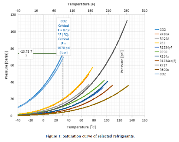
Figure 1 presents the saturation curves of selected refrigerants, demonstrating that CO2 operates at much higher pressures (except for ammonia R717) and exhibits a significantly lower critical temperature than conventional refrigerants used in HP and refrigeration applications. Consequently, CO2-based heating systems typically operate in transcritical mode in most applications. One exception is heat recovery applications in refrigeration systems operating in the subcritical region. In contrast, systems using conventional refrigerants operate entirely within the subcritical regime, where their maximum condensation temperature is inherently limited by the critical temperature of the refrigerant.
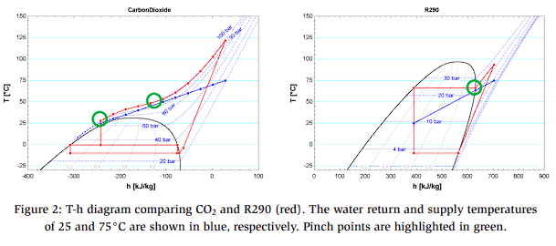
The isobaric and isothermal profiles of CO2 in the supercritical region play a crucial role in determining its heat transfer behavior during heat rejection to the sink medium. Unlike conventional HPs that operate fully in subcritical mode—where the pinch point typically occurs near the refrigerant inlet of the condenser (Figure2, right)—CO2 HPs usually exhibit a pinch point near the midpoint or outlet of the gas cooler (Figure 2, left). A pinch point refers to the location in a heat exchanger design where the temperature difference (ΔT) between the hot and cold streams is at its minimum; the pinch point defines the most constrained heat transfer zone and governs the operating pressure of the HP.
These distinctive thermodynamic characteristics make CO2 a particularly attractive refrigerant for specific heating applications, allowing for high energy efficiency and enhanced performance when operated under the appropriate conditions.
System Layouts
This section provides a brief overview of CO2 HPs and the evolution of their system layouts from basic to advanced configurations. A more detailed discussion of these concepts can be found in Rangelov et al. (2025).
Figure 3 presents the simplest configuration of a transcritical CO2 HP system, which will be used as the baseline for COP comparison with other system layouts. This configuration consists of a single-stage CO2 cycle incorporating a compressor (or compressors), gas cooler, high-pressure valve (HPV), internal heat exchanger (IT receiver), gas bypass valve (GBV), and an expansion valve feeding to a direct expansion (DX) evaporator that typically uses outdoor ambient air as the heat source.
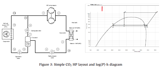
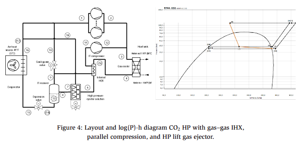
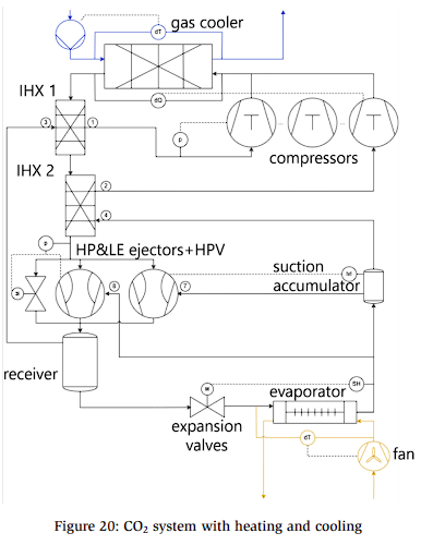
Figure 4 presents an advanced CO2 HP equipped with additional components. These features are described in the following sections.
Additional Features in the CO2 HP System
Internal Heat Exchanger (IHX)
CO2 compressor manufacturers typically require a minimum superheat of 10 K (18°F) at the compressor suction. There are two primary methods of achieving the required superheat:
- Suction regulation: The saturated suction pressure is reduced below the level required by the heat source. This approach is very common but requires additional compressor power and worsens efficiency.
- Superheater/internal heat exchanger: This approach is widely used in CO2 refrigeration applications where additional superheat is necessary. This method improves efficiency by increasing the required suction saturation temperature (SST) due to the reduced evaporator superheat.
Parallel Compressor
Parallel compressors maintain the pressure level in the intermediate (IT) receiver by removing flash gas generated as a result of the pressure drop across the high-pressure valve.
Although the use of a dedicated compressor solely for flash gas removal may appear counterintuitive, this implementation provides a significant energy benefit: system efficiencies are improved by compressing the flash gas from a higher suction pressure instead of routing it to the medium-temperature (MT) compressor suction.
Industry experience indicates that CO2 systems with parallel compression can achieve approximately 7% higher efficiency during transcritical operations compared to standard CO2 cycles (Christensen, 2021).
Ejector Systems
- High-Pressure Lift Ejector: This configuration is the most widely adopted ejector system by certain suppliers of industrial CO2 HPs with capacities above 500 kW (~1,700 kBTU/hr); this configuration is particularly common in Europe. In this configuration, the ejector is driven by throttling the gas from the gas cooler to the IT receiver. The ejector draws gas from the MT level (the source evaporator), mixes it with gas from the gas cooler, and discharges it into the IT receiver (the parallel compression suction level). In effect, the high-pressure ejector reduces the load on the MT compressor line by redirecting a portion of the suction vapor to the higher-pressure IT level. According to experienced European CO2 rack manufacturers, a high-pressure ejector system with a pressure lift of up to 14 bar (~203 psi) offers approximately 5% higher efficiency compared to a parallel compression system integrated with local district heating applications (Christensen, 2021). This configuration has an expected heating COP of ~3.4 compared to the reference system.
- Low-Pressure Lift Ejector: Another ejector configuration used in transcritical CO2 systems is the low-pressure (LP) ejector (Figure 4). This configuration consists of a single compressor suction group operating at the MT level that removes gas from the receiver. Unlike configurations that use a dedicated evaporator compressor, the entire evaporator flow passes through the ejector. The gas from the gas cooler is then mixed within the ejector and discharged into the receiver. The liquid is then supplied to the evaporator, while flash gas is directed back to the compressor(s). An LP ejector system with a 5 bar (~72 psi) pressure lift can achieve ~4% higher COP compared to the parallel compression system (Christensen, 2021), which corresponds to an estimated COP of 3.3 compared to the reference system. This configuration is typically used in smaller transcritical CO2 systems (100–300 kW or 340–1,000 kBTU/hr). However, recent developments in ejector design have enabled this configuration to be implemented in megawattscale CO2 HPs. Some manufacturers have already tested and demonstrated LP ejector solutions for MW-size applications (Clardy, 2023).
Compressor Envelope and Heat Source Temperature
The most widely adopted CO2 compressor technology in the HP industry is the semihermetic reciprocating compressor. These devices have evolved significantly, allowing for the development of megawatt-scale HPs. Modern compressors can now achieve volumetric capacities of up to 100 m³/h (59 CFM) at 50 Hz and about 120 m³/h (70 CFM) at 60 Hz. These advancements extend beyond their size and include substantial improvements in performance and operating envelope.
Typically, the COP of an HP increases with rising SST. However, due to the unique thermodynamic properties of CO2—most notably its low critical temperature of 31°C (88 °F)—this principle reaches its practical limits much faster than other conventional refrigerants. When the heat source temperature is sufficiently high, the corresponding increase in evaporation temperature may exceed the operating envelope of the compressor. Under such conditions, suction pressure regulation at the evaporator level becomes necessary, effectively limiting the maximum allowable SST. Consequently, the compressor cannot fully exploit the potential efficiency gains associated with a higher-temperature heat source.
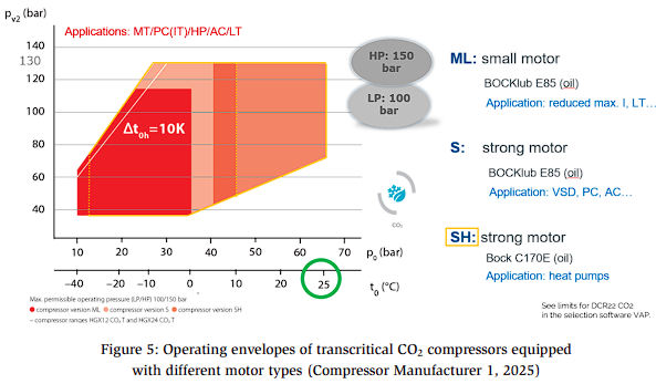
In reciprocating semi-hermetic CO2 compressors, the upper SST limit for the motor typically ranges between 18°C (64°F) and 20°C (68°F). However, some manufacturers have introduced compressors with reinforced motors (i.e., a more powerful drive motor) that extend the operating envelope to 25°C (77°F). Figure 5 presents an example from Compressor Manufacturer 1 (2025), illustrating the envelopes of all compressor models equipped with the SH motor (a strong motor specifically designed for HP and parallel compression applications), which allows for operation at higher suction conditions than standard models.
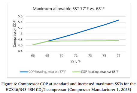
Previous work has demonstrated that higher SSTs result in improved COP (Figure 6).
Control
Heat Sink and Gas Cooler Pressure Control
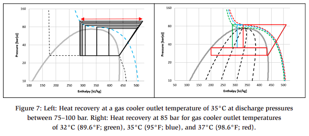
One of the key parameters that governs the performance of CO2 HPs is the water return temperature on the heating side of the system. In conventional HPs using other refrigerants, the condensation pressure is primarily dependent on the water supply/outlet temperature (Figure 2, right). In contrast, CO2 HP and heat recovery systems are strongly influenced by the water return/inlet temperature, which is used to control the gas cooler pressure and optimize heat recovery. This relationship is illustrated in the two P–h diagrams presented in Figure 7.
Figure 7 (left) presents the P–h diagram of a CO2 HP (without a receiver) operating at an evaporation temperature of –10°C (14°F) and a gas cooler outlet temperature (Sgc) of 35°C (95°F), indicated by the dotted blue line. The water return temperature is assumed to be 32°C (89.6°F), corresponding to a temperature difference of 3 K relative to Sgc. The discharge pressure varies between 75 and 100 bar (1088–1450 psi), and the recovered heat is represented by the red arrow. Figure 7 shows that a slight increase in the compressor discharge pressure within certain pressure ranges can lead to a significant increase in recovered heat. Consequently, there exists an optimum pressure at which the heating COP reaches its maximum value.
To demonstrate this behavior, a representative HP with a capacity of 100 kW (340 kBTU/hr) is analyzed from calculations conducted by Karampour and Funder-Kristensen (2024).
The results indicate that, in this example, the optimum COP occurs at approximately 90 bar (1305 psi). This optimum is strongly influenced by the water return temperature and the CO2 gas cooler outlet temperature.
In addition, the difference in capacity and COP between systems with and without a receiver is relatively small (Karampour and Funder-Kristensen, 2024). However, receivers are necessary in CO2 systems since they increase the liquid fraction in the two-phase flow entering the evaporator, thereby enhancing the enthalpy difference across the evaporator. Consequently, for a given heating capacity, the evaporator in a system with a receiver can operate with a lower mass flow rate, smaller size, and higher evaporation temperatures due to its improved heat transfer characteristics.
It should be noted that operation near the critical pressure (73.8 bar; 1070 psi) is not recommended since it results in a low COP and requires a larger evaporator.
Figure 7 (right) describes the heat recovery at 85 bar (1233 psi) for three gas cooler outlet temperatures: Sgc = 32°C, 35°C, and 37°C (89.6°F, 95°F, and 98.6°F, respectively). As shown, lower outlet temperatures result in a higher heating COP (i.e., higher recoverable heat) at the same gas cooler pressure. The Sgc is directly linked to the water return temperature.
Discharge pressure control: Refrigeration
Effective control of the gas cooling pressure is crucial for optimizing the energy efficiency of the system. Typically, an optimization algorithm is used to maximize the COP at each gas cooler outlet temperature.
Figure 8 presents the system performance at discharge pressures of 80, 85, 90, 95, and 100 bar (1160, 1232, 1305, 1378, and 1450 psi, respectively) while maintaining a constant gas cooler outlet temperature of 35 °C (95 °F).
While conventional subcritical refrigeration systems improve efficiency by reducing condensation pressure, transcritical CO2 systems require the control system to actively regulate the discharge pressure for maximum efficiency. In this example, the lowest pressure (80 bar) is suboptimal because the enthalpy difference across the evaporator (represented by the short blue line) is insufficient for high system performance; in this case, increasing the pressure improves the performance of the system.
This behavior highlights the unique thermodynamic characteristics of CO2 systems and their fundamental differences from conventional refrigerants. When operating in transcritical mode, a small increase in pressure increases the enthalpy difference of compression associated with the electricity power input; the COP improves if this increase leads to an even greater enthalpy gain across the heating heat exchangers. The optimum operating pressure is reached when the heating COP is maximized.
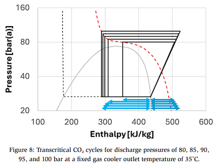
Figure 8 shows that the high-side pressure can be controlled as a function of the gas cooler outlet temperature since these two parameters are independent in the supercritical region. This relationship can be demonstrated by analyzing the COP of a system as a function of different gas cooler outlet temperatures.
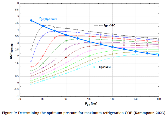
Figure 9 presents the calculated cooling COP as a function of gas cooler pressure for ten different outlet temperatures (denoted as Sgc). The cooling COP is defined as the ratio of the cooling capacity to electrical power consumption. By connecting the maximum COP points of these temperature curves, an optimal relationship can be derived (represented by the blue line).
This simple example illustrates the principles of optimum pressure control. The same fundamentals described here are used to develop the algorithms used to control the discharge pressure under supercritical, subcritical, and transitional operating conditions (Figure 10; Danfoss).
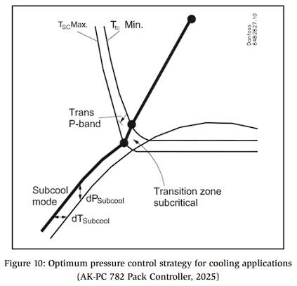
At subcritical temperatures, the system behaves like a conventional refrigeration unit, with subcooling serving as the primary control parameter. Note that active pressure control is typically unnecessary in systems using condensing refrigerants.
As operating temperatures reach the critical point, the control algorithm gradually adapts by increasing the degree of subcooling to ensure a smooth transition between conventional and transcritical operation.
Under transcritical conditions, the system pressure becomes a function of the CO2 outlet temperature from the gas cooler. Here, the primary control objective is to maximize the COP under the prevailing ambient temperature. The gas cooler fans are regulated based on the CO2 outlet temperature: fan speeds are reduced if the temperature falls below a certain threshold. Fan operation is also suspended when all compressors are idle.
Air-cooled gas coolers are commonly used in systems without heat recovery or with only partial heat reclaim. Fin-and-tube gas coolers are typically employed in CO2 applications. Because the refrigerant charge within the gas cooler varies significantly with changes in pressure and temperature, the use of a heat exchanger with a small internal volume is essential to ensure stable and efficient operation.
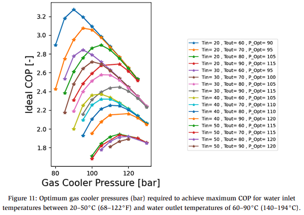
Discharge pressure control: Heating
The optimum gas cooler pressure of a CO2 HP can be determined using the method described in previous sections; these results are presented in Figure 11, which shows that the maximum COP of an HP is primarily governed by the water return/inlet and water supply/outlet temperatures.
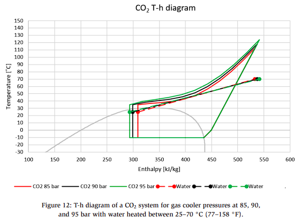
Pinch Point and Water Supply Temperature
The importance of the water return temperature has been discussed in previous sections. In addition, the water supply temperature and the pinch point between the CO2 and water streams are key parameters that govern the high-side pressure of the system. Figure 12 illustrates an example of the heat transfer between CO2 and water in the gas cooler in which the gas cooler outlet temperature (Sgc) is 35°C (95°F), the gas cooler pressures are 85, 90, and 95 bar (approximately 1,233, 1,305, and 1,378 psi), and where the water is heated from 25°C (77°F) to 70°C (158°F) with corresponding pinch points of approximately 0 K, 3 K, and 7 K, respectively.
This example demonstrates the importance of pinch point analysis in ensuring that the temperature difference does not approach zero or negative values, as observed in the case where the system is operating at 85 bar (red line). Such analyses are also essential for determining the maximum achievable water supply temperature for a CO2 HP, which is typically limited to 85–90°C (185–194°F). Furthermore, the results highlight the need to develop an optimal heat recovery or HP control algorithm that simultaneously accounts for the water return temperature, water supply temperature, and the pinch point.
System Comparison: Performance of CO2 Compared to Other Refrigerants
This section compares the performance of CO2 against other refrigerants. This analysis is based on the authors’ previous work; more details can be found in Rangelov et al. (2025).
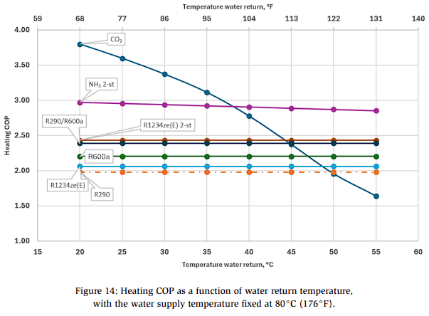
Figures 13 and 14 compare the COP of the HPs as a function of water supply and return temperatures.
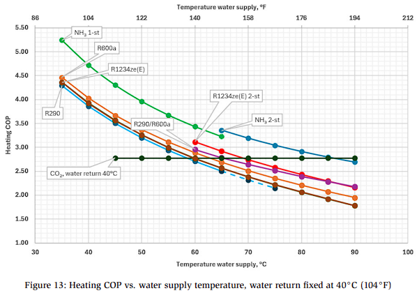
The key findings of the study are summarized as follows:
- Figure 13 shows that, for all systems, the optimal COP is primarily governed by the water supply temperature; however, the CO2 system is less sensitive to this parameter.
- CO2 achieves the greatest efficiency at lower water return temperatures (Figure 14). However, this efficiency declines rapidly as the return temperature rises, and for values above 37°C (99°F), the two-stage NH3 system becomes the most efficient option. The single-stage NH3 system is not suitable under these conditions due to the excessive pressure lift and resultant high discharge temperatures. This limitation is based on the 200 °C discharge temperature limit for the compressor used in the study, beyond which there is either a significant COP drop or it requires that the compressor run outside its operating envelope. The efficiencies of the other systems remain within a similar range to those shown in Figure 14.
- Unlike the trends observed in Figure 13, the COP curves are relatively flat in Figure 14, with the exception of the CO2 systems. This highlights the extreme sensitivity of CO2 systems to water return temperature, with a 2–3% decrease in COP per 1 K increase in return temperature.
- The performance of other refrigerant systems remains relatively unchanged. The NH3 system loses efficiency at higher water return temperatures due to the modeling assumptions made in this analysis: here, the NH3 system is equipped with a dedicated subcooler, whereas subcooling in the other systems is provided solely by an internal heat exchanger (IHX) and therefore depends on the suction temperature, which is held constant in this example.
In summary, CO2 is a highly effective refrigerant for HP applications. Under the right operating conditions, these systems can match or even surpass the efficiency of traditionally superior technologies. The optimal region of performance for CO2 systems is characterized by high temperature lifts on the water side (typically greater than approximately 25 K) combined with low water return temperatures (generally below 35°C/95°F), making it particularly well-suited for such applications.
In addition to system performance, compressor displacement is also considered to be an indicator of the required capital investment. This concept is illustrated in Figure 15.
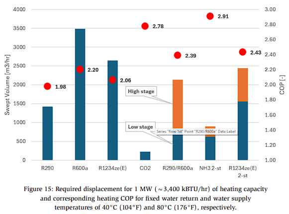
- CO2 requires the smallest compressor swept volume due to its high suction gas density; however, this comes at the cost of significantly higher equipment design pressures compared to all other refrigerants. This is followed by NH3, which benefits from a very high specific enthalpy difference across the evaporator. Consequently, these two technologies require the smallest installed displacement volumes, clearly distinguishing them from the other options. Both technologies also achieve the greatest COPs under the specified conditions, although the relative differences in COP are smaller than the differences in swept volume.
- Among the hydrocarbons, R290 (propane) is the most energy-dense, requiring roughly 2.5 times less compressor swept volume than R600a (isobutane). However, R290 also exhibits a lower COP. A R290/R600a cascade system achieves a higher COP than either refrigerant alone, since the compressors operate at lower pressure ratios, resulting in reduced total power consumption compared to single-stage configurations. The COP of the cascade system is comparable to that of CO2, while its total swept volume falls between that of CO2 and a single-stage hydrocarbon system.
- The performance of R1234ze(E) in a single-stage configuration is similar to that of R600a while requiring a smaller compressor swept volume. The two-stage R1234ze(E) system with an open intercooler achieves approximately 20% higher heating COP and a slightly lower total swept volume compared to the single-stage system. This improvement is primarily attributable to the reduced pressure ratios in each compression stage.
In summary, it is important to consider both the COP and the required swept volume when evaluating HP technologies, since this provides an indication of the compressor size, number of components, and expected service costs over the lifetime of the system. It should be noted that an installed swept volume of 1 m³/h (0.6 CFM) for CO2 represents a larger system capacity and higher equipment cost compared to hydrocarbons or HFOs due to the higher operating pressures and corresponding equipment requirements required for CO2 systems.
Real life Case studies
The two systems presented in this section are examples of CO2-based solutions engineered to provide simultaneous or seasonal heating and cooling, allow for modular capacity expansion, and offer energy-efficient adaptability across a wide range of commercial applications.
Example 1: Commercial CO₂ HP/Chiller in the EU
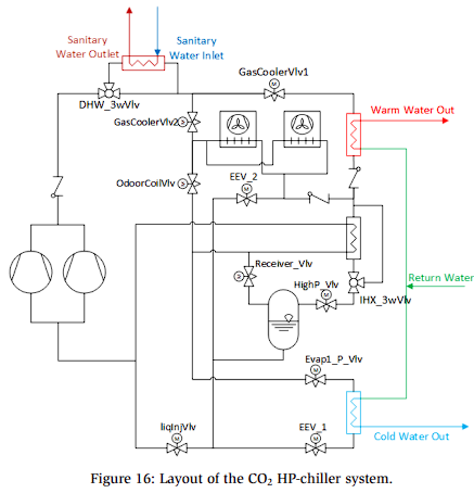
This example is a CO2 HP and chiller system designed to provide space cooling, space heating, and domestic hot water heating with capacities ranging from 50–500 kW (CO2 system manufacturer 1, 2025)2025. A schematic of the system is presented in Figure 16.
The hydronic circuit connecting the heating and cooling plate heat exchangers (PHE) is configured as a three-pipe system in which the cooling and heating loops share a common water return line. The typical water return temperature in this configuration ranges between 20–25°C (68–77°F). The system is capable of producing domestic hot water at 65°C (149°F), regardless of seasonal conditions or the building’s thermal comfort demand.
This functional versatility is achieved through an advanced programmable HVAC control system (Alsmart Control, 2025) that activates or deactivates different sections of the unit and directs or reverses CO2 refrigerant flow using a set of valves. The system represents a unique HP solution that can operate either as an air-source or water-source HP, depending on building demands.
In colder seasons, the system operates as an air-source HP, extracting heat from the ambient air. An advanced hot gas defrost control strategy minimizes the time spent operating the outdoor heat exchanger in defrost mode. Under mild weather conditions, or in buildings with different heating–cooling zones, this system can be partially or fully operated as a water-source HP.
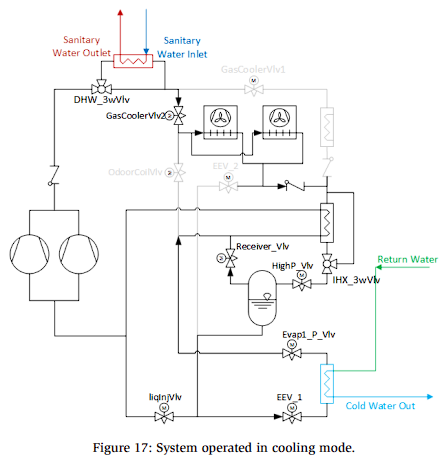
Cooling Mode (Figure 17)
- The PHE chiller heat exchanger is activated when the system operates in cooling mode. Under these conditions, the typical water supply and return temperatures are 7–12°C (44.6–53.6°F) and 20–25°C (68 77°F), respectively. The compressors establish an evaporation temperature and pressure that can meet this demand. The compressor suction pressure is dependent on the temperature of the cold water outlet.
- Heat is dissipated through air-cooled gas coolers located outdoors, i.e., gas cooler valve 1 is closed, and gas cooler valve 2 is opened. The gas cooler pressure is regulated according to an optimization algorithm aimed at maximizing efficiency.
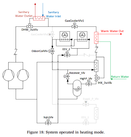
Heating Mode (Figure 18)
- The primary function in this mode is space heating. When the system operates in heating mode, the outdoor air heat exchangers function as evaporators, with ambient air serving as the heat source for the CO2 heat pump. The outdoor air temperature can be as low as -20°C (-4°F).
- Heat is recovered using the space-heating PHE. The water return temperature typically ranges between 20–25°C (68–77°F), while the hot water supply temperature is approximately 45°C (113°F).
- The high-side CO2 pressure is controlled in response to the hot water outlet temperature. An optimization algorithm is used to adjust the high-side pressure based on the hot water supply and water return temperatures.
- Since frost can form on the outdoor heat exchanger under certain conditions, an active defrost mechanism is required.
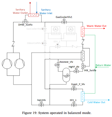
Balanced Mode (Cooling and Heating; Figure 19)
- The system is capable of providing both heating and cooling in this operating mode. Specifically, the PHE chiller generates cooling, while all heat is recovered in the heating PHE.
- The outdoor air heat exchangers are bypassed, and no heat is rejected to the ambient environment.
- The high-side pressure is adjusted according to the hot water supply temperature, while the suction pressure is adjusted to deliver the required cold-water temperature. These adjustments are controlled by the building HVAC management system or the hydronic control system.
- In this configuration, the system can switch between an air–water HP and a water–water HP.
- Operational priority can be given to either balanced cooling or balanced heating.
Example 2: Commercial reversible CO2 HP-Chiller in the USA
This section provides a brief overview of the main functions of this system; a more detailed description is provided in a separate publication by Aschow et al. (2026).
The system is a reversible CO2 HP–chiller designed to provide space heating, space cooling, and domestic hot water for a building HVAC system. The main objective of this product’s development was to achieve a high overall energy efficiency. According to the system designers, this unit is intended to replace conventional water heaters, reduce the need for conventional HVAC equipment, and provide both refrigeration and hot water for process-related applications.
To achieve these objectives, the system incorporates several advanced features, including high-pressure and low-pressure ejectors, variable-speed compressors (both medium stage and parallel compressors), hot gas defrost, an adiabatic gas cooler, fault detection and diagnosis (FDD), and internal heat exchangers.
In addition to the trends and examples described in this paper, further developments will be explored in greater detail in future publications. One such development is the integration of industrial CO2 HPs for waste heat recovery or for combined cooling and heating applications in industrial processes. Another important direction is the deployment of CO2 HPs into district heating networks to replace or reduce reliance on conventional boilers. These systems can utilize air sources for capacities ranging from several hundred kilowatts to a few megawatts, or water sources for capacities extending from a few to several tens of megawatts.
Advansor has installed several air-source CO2 HPs utilizing semi-hermetic reciprocating CO2 compressors that are integrated into district heating thermal grids and microgrids, including a 3 MW (~10,236 kBTU/hr) system in Frederiks, Denmark (Advansor, 2025). Another Danish OEM, Fenagy, has adopted a similar approach for district heating applications, including a 7 MW (~23,884 kBTU/hr) CO2 HP installed in the city of Løsning, Denmark (PFAS free Cooling Heating, 2024). The adoption of such energy system solutions has extended beyond Europe; for example, Vitalis in Canada recently commissioned a 1.5 MW (~5,118 kBTU/hr) reversible air-source CO2 HP at the University of British Columbia’s Okanagan campus in Kelowna (Natural Refrigerants, 2024).
Conclusions
This paper has examined several key aspects of CO2-based heating and cooling systems. In particular, the unique thermophysical properties of CO2 have been analyzed, emphasizing its suitability and advantages in specific heating applications. Indeed, its favorable heat transfer characteristics make it an attractive choice for HP systems when the thermal boundary conditions of CO2 and heat carrier (most commonly water) are well matched.
Two system layouts were presented: a standard configuration and an advanced system design. These layouts illustrate different approaches to improving performance and efficiency depending on the application and operational requirements. Control strategies were also examined, with particular focus on the high-pressure control strategies used in CO2 refrigeration and HP systems. This comparison provides insights into how different control methods can affect system efficiency and stability, emphasizing the importance of optimal control in maximizing performance.
The influence of water temperature boundary conditions was also discussed, demonstrating how the temperature differences between the water supply and water return streams, as well as the water return temperature, have a significant impact on overall system performance. In particular, higher temperature differences and lower return temperatures were shown to favor CO2 HP operation. Component availability, especially compressors, was identified as another important factor. CO2 compressors are becoming larger, more efficient, and capable of providing heating at capacities ranging from hundreds of kilowatts to several megawatts. The importance of the compressor envelope and extended suction temperature range was emphasized, as these features allow for effective heat recovery from high-temperature sources. In addition, the use of large compressors as parallel units was discussed as a means of enhancing system flexibility and performance.
A comparative analysis summarizing findings from previous research demonstrated the heating performance of CO2-based HPs relative to systems using conventional refrigerants. The results showed that CO2 systems offer superior efficiency in certain heating applications. Furthermore, two practical examples of advanced reversible CO2 HP–chiller systems for HVAC applications and DHW production were introduced, with successful operation demonstrated in both Europe and the United States. These examples demonstrate the growing maturity and commercial viability of CO2-based technology.
In conclusion, CO2 is a unique and highly efficient refrigerant that is particularly suited for integrated heating and cooling applications. Its successful deployment depends on intelligent system design and smart control strategies that focus on optimal pressure and temperature management. With ongoing technological advancements, CO2 systems are expected to become an even more prominent and effective solution in the global transition toward low-carbon heating and cooling technology.
References
Advansor, 2025. 3 MW heat pump for Frederiks District Heating Plant. URL https://www.advansor.com/case-frederiks-district-heating
AK-PC 782 Pack Controller, 2025. . ADAP-KOOL® pack controllers – for efficient control and operational reliability, available at: https://www.danfoss.com/en/products/dcs/electronic-controls/pack-controllers/#tab-overview.
Alsmart Control, 2025. . High-Performance HVAC Programmable Controllers, available at: https://www.danfoss.com/en/products/dcs/electronic-controls/programmable-controllers/alsmart/#tab-overview.
ANSI/ASHRAE, 2019. Designation and Safety Classification of Refrigerants – Standard 34-2019.
Atmosphere, 2023. Natural Refrigerants: State of the Industry; available at: https://atmosphere.cool/product/natural-refrigerants-state-of-the-industry-2023-edition-free/.
Christensen, K., 2021. CO2 varmepumper fra Fenangy A/S, Presentation at: Dansk Fjernvarme,Temadag om store kollektive, 19-05-2021.
Clardy, P., 2023. Danfoss CO2 Ejectors for Industrial Applications; Retrieved from https://www.youtube.com/watch?v=Wz4OGiTwr6c.
CO2 system manufacturer 1, 2025. Triple Aqua natural refrigerant heat pump. available at: https://www.tripleaqua.com/.
Compressor Manufacturer 1, 2025. Semi-hermetic CO2 compressors: HGX CO2-series, available at: https://www.danfoss.com/en/products/dcs/compressors/compressorsfor-refrigeration/semi-hermetic reciprocating-compressors/semi-hermetic-co2-compressors-hgx-co2-series/.
EPA, 2024. Background on HFCs and the AIM Act; available at: https://www.epa.gov/climate-hfcs-reduction/background-hfcs-and-aim-act.
Karampour, M., 2023. CO2 as refrigerant in cooling and heating applications, available at: https://www.danfoss.com/en/about-danfoss/articles/dcs/expert-paper-co2-asrefrigerant-in-cooling-and-heating-systems/.
Karampour, M., Funder-Kristensen, T., 2024. Heat recovery and heat pump applications using CO2 as refrigerant, in: 16th IIR Gustav Lorentzen Conference on Natural Refrigerants. College Park, Maryland, USA.
Natural Refrigerants, 2024. Vitalis Shares More Details About Its CO2 Heat Pump District Energy Project at the University of British Columbia. URL https://naturalrefrigerants.com/news/vitalis-shares-more-details-about-its-co2-heat-pumpdistrict-energy-project-at-the-university-of-british-columbia/
PFAS free Cooling Heating, 2024. In 9 Months, Fenagy Built and Connected a 7MW CO2 Heat Pump to a Town’s District Heating Network. URL https://pfasfreecoolingheating.eu/in-9-months-fenagy-built-and-connected-a-7mw-co2-heat-pump-to-a-towns-district-heating-network/
Rangelov, I., Karampour, M., Lund, T., 2025. CO2 Heat Pumps: System Solutions and Applications Mapping. Presented at the IIAR Natural Refrigeration Conference & Heavy Equipment Expo, Phoenix, Arizona.