2026 Tech Paper: The Reverse Piston Design: Taking the Load Off High-Pressure Refrigeration and Sustainability Challenges
Author:
Michael Gersmeyer
Abstract
The industrial refrigeration and heating industries are increasingly affected by the transition to low–global warming potential (GWP) refrigerants and decarbonization initiatives. Consequently, industrial refrigeration and heating applications now often require high suction pressures due to their use of low-GWP refrigerants such as NH3 or CO2. To address this challenge, new compressor designs must be used to extend bearing life and increase the intervals between maintenance downtimes. This paper presents a novel design that reduces bearing loads, prolongs compressor life, and improves system uptime while reducing maintenance costs.
Introduction
Industry Trends and Background
With the transition to low-global warming potential (GWP) refrigerants and the increasing emphasis on decarbonization, the industrial refrigeration and heating industries have been actively seeking solutions that utilize environmentally friendly refrigerants. CO2 is one example of such a refrigerant; however, CO2 systems require relatively high working pressures, and, in many applications, require high suction pressures compared to conventional refrigerants.
Problem
High suction pressures in refrigeration compressors can impose a significant load on compressor components, including bearings. Specifically, high suction pressure can generate significant axial loads in screw compressors, leading to accelerated wear in thrust bearings, reducing their service life; in some scenarios, this reduction can be significant. Severe bearing wear can lead to the shutdown of refrigeration systems for maintenance in order to replace or repair damaged bearings. Such shutdowns are costly due to labor required to perform maintenance, the cost of replacement parts, and the loss of production during the downtime.
For several decades, various methods have been used to mitigate high axial loads on bearings in screw compressors. These methods include larger bearings, specialty bearings, additional bearings, and balance pistons; however, these solutions are often complex or costly.
For example, the use of larger or additional bearings is not always feasible: this solution requires physical space that may not be available within the housing of compact machine designs. Specialty bearings can be employed, but are often costly.
Although these methods can increase the service life of bearings, they do not address the root cause of the problem, the high axial loads. Consequently, acceptable bearing life may still not be achieved when employing these methods.
Traditional balance pistons often have a rotating piston that is attached to the end of the rotor. The piston fits within a cylinder sleeve that guides the piston and forms a pressurized cavity. High-pressure oil is supplied to the piston, producing a force that opposes the axial load on the rotors, thereby eliminating some of the axial load applied to the thrust bearing. In twin screw compressors, balance pistons can be used on the male rotor, female rotor, or both.
However, suction pressures can decrease dramatically when compressors are unloaded. Under such conditions, the bearings may become overloaded by the high-pressure oil. To prevent this, the high-pressure oil must be regulated by a set of valves, orifices, and in some cases, electronic closed-loop controls. These control methods can be complex and costly.
Consequently, a simple solution was required to significantly increase bearing life.
Proposed Solution and Description
Single-screw compressors are designed such that the compression forces are balanced. This can be seen in Figure 1, where the forces F comp 1 and F comp 2 are equal and opposite along the axis of the screw rotor. Therefore, these forces cancel each other out. There are other forces created by the compression cycle in the axial direction. However, these axial forces due to compression are negligible and will therefore be considered zero for this paper.
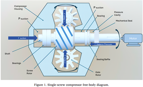
The remaining axial force acting on the assembly is generated by the suction pressure, labeled as P suction in Figure 1. Note that P suction acts on the end of the shaft opposite the motor. The opposite end of the shaft extends through the compressor housing, where it is coupled to the motor. Consequently, the only force generated by the suction pressure in the axial direction is F suction, which acts on the leftmost end of the shaft.
In contrast, the reverse piston design offsets F suction by employing a sealing baffle that creates a pressure cavity. The sealing baffle is keyed to the screw rotor shaft of the single screw compressor, causing it to rotate with the screw rotor. The pressure cavity fills with oil that is used to lubricate the bearings and the mechanical seal. A labyrinth seal on the sealing baffle holds the oil within the pressure cavity.
When F suction increases due to increasing suction pressure, the F balance pressure also increases. The F balance pressure opposes F suction such that the axial loads experienced by the bearings are significantly reduced.
Examples of Bearing Life Increase
The following calculations and scenarios illustrate the effect of suction pressure on bearing life. The axial force generated by suction pressure is the product of the cross-sectional area of the shaft multiplied by the suction pressure. For a shaft with a diameter of 2.5” operating at a suction pressure of 300 psi:
F suction = As × Ps, where As is the Shaft area and Ps is the suction pressure
F suction = π * (2.5″/2)2 * 300 psi=1,472 lbs
An axial force of 1,472 lb represents a significant load that can lead to reduced bearing life when the compressor is operating continuously.
Table 1 presents a few feasible scenarios and the resulting increase in bearing life.
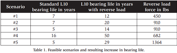
Table 1 shows that a load of 1472 lb. can be substantially counteracted by the reverse load generated by the reverse piston design.
Examples of Designs That Increase Bearing Life
Bearing life has long been a concern in screw compressors. This section provides a description of several designs used in the industry to increase bearing life. The intent of this section is not to present a complete technical description of each design, but rather to provide some context on recent developments in the industry.
Balance Mechanism with Slide Bearing
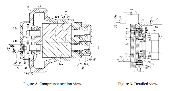
The following configuration was designed by Takaki et al. (2015), which uses a thrust plate located at the end of the rotor shaft to limit the thrust force transmitted to the bearing. This component is represented by item 46 in Figure 2. The amount of thrust can be adjusted depending on the pressure differential between the suction and discharge pressures. The adjustment is carried out by a control unit that is comprised of pressure sensors and a control unit, represented by item 80 in Figure 3.
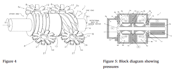
Bilaterally Symmetric Screw Compressor
This configuration was designed by Hossain et al. (2015) and comprises a single screw rotor with two sets of grooves. Inlet ports are located near both ends of the rotor, while the discharge ports are positioned near the center. This symmetrical design balances the axial forces on the rotor, reducing the load imparted onto the bearings. However, this approach requires additional machining and gate rotors, increasing the overall cost of this design.
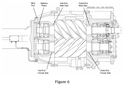
Balance Piston for Twin-Screw Compressors
This approach uses control panels to monitor pressure and adjust the oil pressure as needed to ensure that the bearings are not overloaded (Johnson Controls, 2022). This design requires multiple balance pistons, while the control system can be complex and costly.
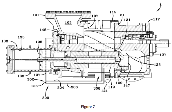
Compressor With Balance Piston Using Slide Valve Position to Adjust Balance Pressure
In this design, a fluid source provides pressure to the balance piston (Nemit, 2014). However, the equipment to regulate the pressure may include a controller, solenoid valves, algorithms, a pressure transducer, and a feedback mechanism. This apparatus can be complicated and expensive.
The complexity of this design can be reduced by regulating the pressure acting on the balance piston (item 145, Figure 7) using the position of the capacity slide valve. When the compressor is unloaded, the fluid pressure applied to the balance piston is reduced, thus reducing the force of the balance piston and the load on the bearings during unloaded operations.
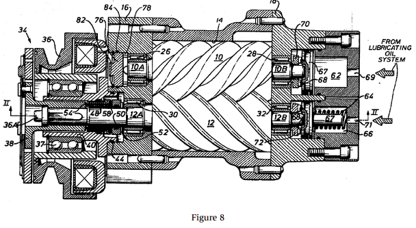
Balancing Piston Device
This design uses balancing pistons (item 67, Figure 8) that exert a biasing force on screw rotors (Schibbye et al., 1976). The force is generated by oil pressure entering at location 69 and the pressurizing cavity at location 62 (Figure 8). The oil is supplied from the lubricating system.
The oil pressure in this system must be regulated to ensure that the rotors are not overbalanced or underbalanced. Therefore, a regulation system would need to be used (not shown in this figure). The regulation system can be controlled using valves, orifices, or closed-loop electronic controls.
Conclusion
Higher working pressures in compressors can generate substantial bearing loads, thereby significantly reducing bearing life. The reverse piston design attempts to mitigate this issue, leading to significantly increased bearing life. This is accomplished by pressurizing a cavity with oil pressure that is already supplied by the compressor system. The pressure cavity generates a reverse load that counteracts much, and in many cases nearly all, of the load imparted by the suction pressure acting on the main rotor shaft. By offsetting the force generated by the high suction pressures, the bearing load is reduced and bearing life extended. The implementation of this design can lead to reduced maintenance costs for industrial refrigeration and heating operators that aim to utilize low-GWP refrigerants such as CO2.
References
Hossain, M. A., Masuda, M., & Ohtsuka, K. (2015). U.S. Patent No. 8,992,195. Washington, DC: U.S. Patent and Trademark Office.
Johnson Controls. (2022). Balance piston for twin screw compressors. Retrieved February 28, 2026. https://docs.johnsoncontrols.com/industrialrefrigeration/r/FRICK/en-US/SGC/SGX-Rotary-Screw Compressor-IOM-MK2/2022-02/2022-02/Installation/Oil-System-Requirements/Balance-piston-oil-requirements-and-regulations
Nemit, P. (2014). Compressor – U.S. Patent No. 8,641,395 B2. Washington, DC: U.S. Patent and Trademark Office.
Schibbye, H., & Englund, A. (1976). U.S. Patent No. 3,932,073. Washington, DC: U.S. Patent and Trademark Office.
Takaki, S., et al. (2015). Compressor – U.S. Patent No. US 2015/0118092 A1. Washington, DC: U.S. Patent and Trademark Office.