2026 White Paper: Vibration Failure Risk of Piping and Tubing
Author:
Walter Kelm, PE, Kelm Engineering, LLC
Abstract
All compressors produce some vibration in the connected pipe and tubing, but how much is too much? Excessive vibration can lead to unexpected leaks that can cause hazardous situations and
loss of cooling. In many food applications, loss of cooling results in significant product loss in addition to direct maintenance and repair costs. This paper provides a technical overview of tubing vibration measurement, assessment, and failure risk. Guidelines will be provided to screen operating systems, as well as design guides to prevent vibration issues.
The refrigeration industry does not have specific vibration requirements for tubing and piping. However, there are well-established limits from other industries (e.g., the ASME Pressure Vessel Code, the American Petroleum Institute, the International Organization for Standardization, and the Energy Institute). General industry standards will be referenced to provide suggested language for purchasers to use in specifications to minimize the risk of vibration-related failures.
Introduction
Piping and tubing are critical components of all refrigeration systems. They contain the refrigerant and allow the compressor to drive flow through the system, leading to heat transfer. While a refrigeration system operates, the piping is subject to dynamic forces from the compressor and fluid flow, which cause pipe vibration. All refrigeration systems will experience some vibration; however, excessive vibration can lead to ailure of piping and tubing. Any failure of the piping system results in refrigerant loss, and the system must be shut down. In addition to system downtime, refrigerant leaks can present safety or environmental hazards. Therefore, it is critical to apply good design practices for piping and tubing and to assess operating refrigeration systems for excessive vibration.
Vibration Background
Vibration is a back-and-forth motion around a central position. Whenever a component, such as piping, repeatedly moves between two points, it is vibrating. Vibration theory can be quite complex, but for our review, there are two key characteristics: frequency and amplitude. Frequency is the rate at which a vibration occurs over time. It is typically measured in Hertz [cycles per second] or CPM [cycles per minute], the number of cycles that happen within a given time period. The amplitude describes the magnitude of the motion and is expressed in physical units such as displacement, velocity, or acceleration. It is critical to ensure that the vibration amplitude units used are consistent when measuring and applying limits.
Frequency is an essential part of understanding a vibrating system. Every mechanical system will have different vibration characteristics at different frequencies. An intuitive way to think about frequency is to consider musical notes. Lower notes have a lower frequency and higher notes have a higher frequency. Although different musical notes may have the same intensity, when they have different frequencies, they are perceived differently and have different impacts on systems.
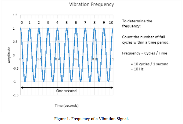
The frequency can be determined by counting the number of full cycles that occur within a time period. Figure 1 shows an example of determining the frequency from a vibration signal. Ten cycles are counted in one second, giving a frequency of 10 Hz.
The vibration amplitude can be described in terms of displacement, velocity, or acceleration. The displacement is the distance that the vibrating component moves and is typically given as mils or microns peak-to peak, which is the full distance that the vibration cycle covers. The velocity is the speed of the part and is given in units of inches per second [in/s, peak] or millimeters per second [mm/s, rms]. The acceleration is the rate of change in velocity and can be given in units relative to gravity [G’s, rms], inches per second squared [in/s2, rms], or millimeters per second squared [mm/s2, rms].
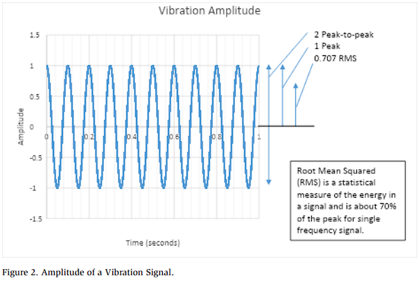
The amplitude is commonly given in reference to the peak-to-peak [pk-pk], peak range [pk], or root-mean-square [rms] value. Figure 2 shows what these terms represent. Peak-to-peak is the full range from the minimum to the maximum. Peak is the height from zero to the maximum. Root mean square (RMS) is a statistical measure of the energy in a signal and is calculated by finding the standard deviation of the values in a vibration signal. Current international standards for acceptable vibration tend to use RMS. However, for historical reasons, pk-pk and pk are often used to denote displacement and velocity, respectively.
In practice, all vibration tools can automatically convert between the units used to measure vibration. The important thing to remember is that it is critical to be consistent with the measurement units and the analysis criteria. It is great practice to always list the vibration amplitude units when documenting vibration results to ensure consistency.
Vibration Response
The vibration of a mechanical system, such as piping, is a combination of the applied forces and the response due to its properties. When high vibration occurs, there are two approaches to reducing the vibration. The first approach is to reduce the forces by upgrading the compressor or adding pulsation reduction hardware. Because this approach directly reduces the source of the vibration, it is the most reliable way to achieve vibration reduction. The second approach is to change the response of the system by adding supports (mass and stiffness) or increasing friction (damping). Changing the mechanical system affects the vibration response but keeps the forces the same, which can increase or decrease the vibration, depending on the specific changes.
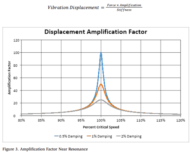
Every mechanical system has natural frequencies that amplify its vibrational response. When a compressor operates at a speed that coincides with the natural frequency of the system, the system can amplify the vibration, causing a resonance; this is commonly called the critical speed. Operating at a critical speed can lead to dangerous levels, and many variable speed compressors require speed block-out ranges to avoid critical speeds. The vibration displacement is given by the formula below. The amplification factor is graphically shown in Figure 3
The natural frequencies of a piping system can be estimated for simple layouts, but more complicated routing requires a computational simulation. In 1990, Wachel et al. published simple equations with lookup tables to estimate the natural frequencies for typical piping and tubing. This method allows a simple design review for a pipe or tube arrangement regarding the support spacing. For the most common layout of a pipe/tube span between simple supports, the first natural frequency of the pipe can be estimated using the formula below. This formula works well for straight sections, as well as those containing one or two bends, as long as the pipe or tube diameter remains constant. When there are diameter changes or large components such as valves, the formula is no longer valid. This formula can also be arranged to give the spacing support required to achieve a target pipe natural frequency. When the primary vibration frequency of a compressor is known at the design stage, this formula can be used to determine the necessary spacing and number of pipe/tube supports. When using this equation to design supports, it is standard practice to apply a 20% safety margin to ensure that the natural frequencies exceed the primary operating frequency of the compressor.
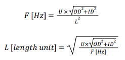
Where:
F [Hz] is the actual or target natural frequency. Standard practice is to use
F [Hz] = 1.2 × the known compressor vibration frequency.
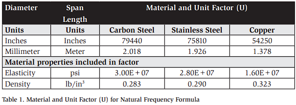
U is the appropriate unit and material factor from Table 1.
OD and ID are the outer and inner diameters of the tube or pipe, respectively.
L is the pipe/tube span length between supports, measured as the linear length of pipe/tube.
Design Recommendations
In a refrigeration skid, most compressors generate pressure pulses that drive the highest piping vibration. For each compressor model, there will be a primary pulsation frequency determined by the compressor details. This is often 2–5 times the running speed. The necessary piping support spans can be determined based on the known compressor pulsation frequency and the pipe or tubing details.
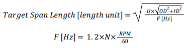
where N is the compressor pulsation harmonic. If unknown, a conservative value of 5 can be used.
Fatigue Failure
Excessive vibration can cause high bending stress, leading to high cycle fatigue. The fatigue risk of piping ultimately depends on the stress amplitude, which is determined by the vibration amplitude, the pipe layout, and the allowable stress for the material. Some arrangements and piping components will experience failure at lower vibration amplitudes due to increased stress.
Specifically, threaded fittings and changes in geometry (e.g., tees, fittings, and valves) are common locations for stress intensification. ASME B31J-2023 is a piping design code that includes specific stress intensification factors (SIFs) for various pipe configurations. For a given pipe layout, engineering design tools can be used to calculate the stress induced by a given vibration level. In general, the highest-risk locations for failures are threaded connections on heavy valve components. Away from significant added mass and stress concentrations, the piping and tubes see lower stress for the same level of vibration.
Vibration Measurement
Vibration is a dynamic, oscillatory motion typically too small to be seen by the naked eye and requires specialized instrumentation to measure. Vibration sensors measure either the displacement, velocity, or acceleration. Displacement sensors, called proximity probes, are typically used for large, high-speed turbomachinery but are not very common for refrigeration systems. Sensors that directly measure velocity are uncommon. Piezoelectric accelerometers are the most commonly used sensors for measuring piping vibration, but the acceleration signal is typically integrated into velocity when the results are assessed.
Motion amplification cameras are a relatively new technology for detecting piping vibration that use high-speed, sensitive cameras to capture vibration in pixel data. Motion amplification can be used as a visual tool to quickly identify piping locations with high vibration. However, they have limitations due to lighting, viewing conditions, and frequency range. The variation in pixel data and the distance to the target are used to determine the vibration magnitude; inaccuracies can result from poor lighting or a complicated view. The most significant limitation occurs at higher vibration frequencies, which can occur with reciprocating and screw compressors. When the primary vibration frequency exceeds the range of the camera sensor, the vibration cannot be measured.
For piping vibration, the best approach is to identify high-vibration locations using operator experience, a motion-amplification camera, or a vibration survey. Then, high-vibration locations should be measured with accelerometers to assess the severity.
Variable speed compressors are particularly challenging for vibration measurement because, at different speeds, the vibration characteristics of the skid can change, and some locations may exhibit higher vibration at some speeds than others. For a variable speed skid, the piping vibration must be assessed at all locations and speeds to sufficiently identify vibration risk. Even if the vibration is acceptable at maximum speed, a reduced speed may likely have a critical speed that results in amplified piping vibration.
Vibration Assessment
The allowable vibration for piping and tubing depends on the material, layout, and stress intensification. However, screening thresholds are widely used across the industry to evaluate piping. These screening criteria typically use a relatively low screening threshold acceptable for all piping arrangements that meet typical pipe design criteria. Then, for any pipe sections exceeding the screening threshold, a detailed layout review is required to determine acceptable vibration levels. For simple pipe or tube layouts, this can be estimated based on experience, but for more complex layouts, an engineering review is required to evaluate the stress per vibration.
There are multiple conflicting references for identifying an acceptable screening threshold. The most conservative, commonly used screening threshold is defined in ASME OM3:2022, an ASME standard for the operation and maintenance of nuclear power plants. ASME OM3:2022 defines an allowable operating pipe vibration of 0.50 in/s pk as well as a calculation procedure for identifying a higher allowable vibration in some scenarios. The International Organization for Standardization (ISO) defines piping vibration limits for reciprocating compressors in ISO 20816-8. Wachel et al. have defined another set of screening criteria based on experience in typical industrial piping settings. Finally, the Energy Institute (2008) has defined another set of vibration criteria based on failure history in the UK offshore oil and gas industry. These limits are plotted in Figure 4. There is a wide range of “acceptable” values based on typical pipe arrangements and accepted levels of risk across industries.
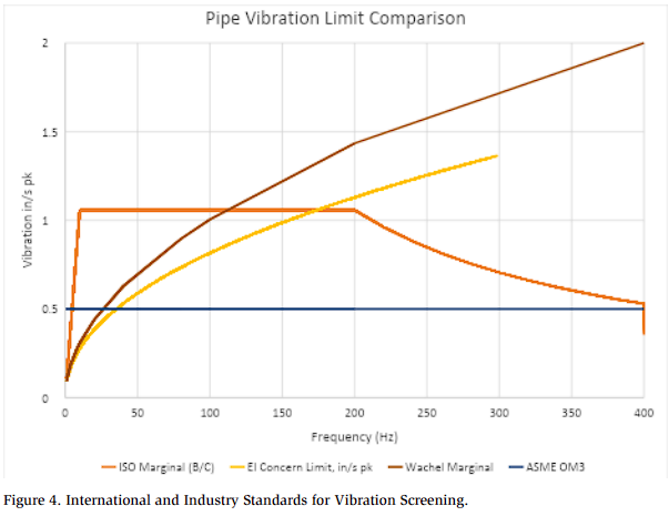
High cycle fatigue failure is a probabilistic failure mechanism and can vary even for equivalent systems operating at similar vibration levels. Therefore, determining the acceptable pipe vibration limit depends on the service hazards, equipment criticality, and financial impact of repairs. For toxic refrigerants, such as ammonia, in a critical service, it may be appropriate to use the nuclear industry target of 0.5 in/s pk. However, achieving very low vibration can require significant supports or modifications during commissioning, and the cost may be prohibitive. Many refrigeration skids have operated with pipe vibration levels of 1 in/s pk or higher; in such cases, the end user is operating at an increased risk that they may not be aware of.
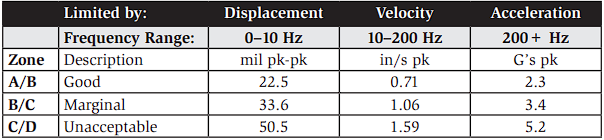
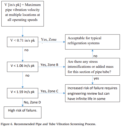
Figures 5 and 6 show a proposed vibration screening for piping and tubing that can be implemented using a handheld vibration meter with an integrated accelerometer to yield vibration velocity in inches per second peak [in/s pk]. Most refrigerationrelated vibration occurs between 20–400 Hz, depending on the specific compressor, but measuring accurate vibration velocity below 10 Hz may require specialized equipment and has a lower velocity threshold.
Once the maximum vibration for a section of piping or tubing is identified, it should be compared with the defined screening limits. For typical refrigeration piping and tubing, the limits defined in ISO 20816-8 are intended for reciprocating compressors and provide a reasonable target for vibration. If the vibration is less than 0.71 in/s pk, then a low fatigue risk (infinite design life) is expected for typical refrigeration installations. If the vibration is up to 1.06 in/s pk, it may be acceptable, provided there are no stress intensifiers or lumped masses (heavy, unsupported valves or filters) connected to that pipe section. Vibration up to 1.6 in/s pk may be acceptable in certain situations, but it requires an engineering review. Pipe vibration exceeding 1.6 in/s pk is a significant fatigue failure risk and requires immediate changes to an operating refrigeration system. Common short-term modifications include limiting compressor speeds to avoid operating at natural frequencies or adding pipe supports to brace the pipe. However, adding pipe supports must be done in a way that allows sufficient thermal flexibility for sections that experience heat or cold. Unfortunately, controlling vibration and allowing thermal growth often represent competing design objectives.

Traditional Approaches to Reduce Vibration
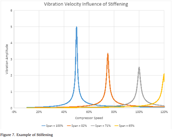
The most common approach to addressing elevated piping vibration is to add supports. The natural frequency and resulting vibration depend on the span between effectively rigid supports. Unless included in the original design, it can be challenging to add sufficient supports to a refrigeration skid. For example, if the piping for a variable speed compressor was designed with a natural frequency that occurs at 50% speed, shifting the natural frequency to 120% or higher would require doubling the number of pipe supports. Otherwise, adding supports would simply change the speed at which the high vibration occurs. Figure 7 shows the effect of changing the pipe span and the relative vibration on the velocity. Without identifying the necessary supports in advance, field-modifying piping can feel like a never-ending battle.
Conclusions
The piping and tubing vibration problems commonly encountered in refrigeration systems have been discussed. Piping vibration is driven by forces from compressor pressure pulsation and amplified by the natural frequencies of the piping system. Modifications to pipe supports on existing refrigeration skids can be very challenging and costly. At the design stage, vibration risk can be significantly reduced by ensuring that the piping is adequately supported by selecting a pipe support span that targets a design frequency above the expected compressor pulsation frequency.
When a refrigeration skid is commissioned, the operating vibration levels of the piping and tubing should be measured. A handheld vibration meter should be used to check vibration at multiple locations, speeds, and operating conditions to determine the maximum vibration. The vibration should be compared to the proposed vibration screening limits or other industry standards. Any vibration exceeding the proposed screening limits should undergo an engineering review to determine its acceptability for the specific layout.
General design recommendations to minimize piping vibration:
- Avoid unreinforced branches or threaded connections
- Branch connection fittings without stress intensification should be used for all branch lines
- Use pipe supports that allow some damping
- 100% metal pipe/tube systems (welded, soldered, or brazed) have very low damping and will have very high response at resonances
- Clamps and supports that include rubber or allow some friction will generally provide some level of damping
- Instrument connections, relief valves, vents, and drains should be reinforced to the main pipe to prevent relative vibration
- Avoid unnecessary changes in direction and limit as many fittings as possible
- A straight pipe cannot produce dynamic forces from pulsations
- Avoid long overhangs and long unguided risers
- Pipe should be run at grade as much as possible to produce more rigidity in supports
- Supports should be as stiff as the pipe they are connected to
- Branches in the pipe should be located as close to supports and fixed ends as practical
- Supports should be located near heavy valves and at piping discontinuities
- Thermal growth must be considered when selecting support locations.
References
American Society of Mechanical Engineers (ASME). (2022). Operation and maintenance of nuclear power plants (ASME OM3:2022).
American Society of Mechanical Engineers (ASME). (2023). Stress intensification factors (i-factors, flexibility factors (k-factors), and their determination for metallic piping components (ASME B31J-2023).
Energy Institute. (2008). Guidelines for the avoidance of vibration induced fatigue failure in process pipework. 2nd ed. Energy Institute.
International Organization for Standardization (ISO). (2018). Mechanical vibration — Measurement and evaluation of machine vibration — Part 8: Reciprocating compressor systems (ISO 20816-8).
Wachel, J. C., Morton, S. J., & Atkins, K. E. (1990). Piping vibration analysis. In Proceedings of the 19th Turbomachinery Symposium (pp. 11–26). Texas A&M University, Turbomachinery Laboratories.