


2022 Technical Paper #13
Liquid Overfeed Ammonia Refrigerating Plant and Energy Efficiency
Author:
Stefan S. Jensen, Managing Director, Scantec Refrigeration Technologies Pty. Ltd.
Abstract
The global HFC phase-down and the proposed restrictions on PFAS (per- and polyfluorinated alkyl substances) have accelerated the transition towards natural refrigerants. The requirements of the Paris Agreement, the European CBAM (Carbon Border Adjustment Mechanism) initiative, and ESG (Environmental, Social, Governance) have combined to elevate the ranking of system energy efficiencies in decision-making processes. Energy performance benchmarking for certain refrigeration applications is emerging in various polities and sectors. The benchmarking is often technologyagnostic and challenges long-held conventions and energy-efficiency engineering capabilities. This will continue and will force critical reviews of all refrigeration system design conventions. One such system is the liquid overfeed concept that will celebrate its centenary in 2025. This paper presents energy performance records from refrigerating plants servicing several refrigerated warehouses and provides evidence that the presence of high-density liquefied refrigerant in complex suction line networks of expansive plants may cause more energy waste than previously thought. This paper seeks to quantify the energy performance penalties associated with liquid overfeed through comparisons of near-identical practical installations where the only significant difference is the presence (or not) of liquefied refrigerant in the suction line network. Finally, this paper presents a small selection of practical business cases that demonstrate the economic viability of design interventions targeting maximization of energy efficiency.
Introduction
Liquid recirculation refrigerant feed, often also referred to as liquid overfeed, was patented in 1925 to YORK Corporation (Briley, 2004). It was not until the 1950s and 1960s that demand for frozen foods had grown to such an extent that investments in large and very large freezing plants became economically viable. Such large-scale freezing plants remain in existence now. Liquid overfeed refrigerant feed remains the dominant feed method by far, including in the new ammonia-based freezing and refrigerated storage plants being designed and implemented today.
Most ammonia refrigeration plant practitioners and, perhaps, educators, are of the view that liquid overfeed will deliver superior energy efficiency compared with dry expansion refrigerant feed—a refrigerant feed method commonly used in commercial refrigerating plants and air conditioning systems. This also implies that they assume the energy performance penalties associated with saturating wet return lines and risers with high-density liquefied refrigerant to be negligible, which is counterintuitive. According to Marcinichen and Thome (2019), pressure drops in pipelines containing a liquid/gas mixture can be up to sixty times greater than in equivalent pipelines conveying vapor only. The common view favoring liquid overfeed has likely evolved over several decades of unsuccessful attempts at making dry expansion NH3 refrigerant feed work as intended in industrial refrigerating plant. These experiences may well have encouraged designers, contractors, and consultants to adopt the most forgiving and, apparently, least problematic solution—liquid overfeed.
Within any sector, questioning of a convention unchallenged for more than half a century will almost universally be met with high levels of skepticism. One calls to mind Galileo Galilei, who spent the rest of his life in house detention after the Inquisition found him “vehemently suspect of heresy” in return for his championing of Copernican heliocentrism (Earth rotating daily and revolving around the sun).
Over the last decade or more, a considerable number of low-temperature, centralized, low-charge ammonia refrigerating plants and other types of systems eliminating liquid in suction lines have been installed in several countries. In addition, energy performance comparisons between these “dry” systems and conventional liquid overfeed plants are emerging, and considerable energy performance advantages of “dry” systems are being signaled. Isolating the elimination of wet return line pressure drops from other energy efficiency engineering measures is difficult with currently available theoretical modeling tools because there are no correlations for wet riser pressure-drop estimation during flow reversal (Ku < 3.2) (Nitschke and Jensen, 2019). Therefore, this paper focuses on comparing recorded energy performances of near-identical commercially operating refrigeration systems where the main difference is the presence (or not) of liquefied refrigerant in the suction line network.
Low-charge NH3 Technology
The definition of low-charge NH3 technology differs depending on geography, application, companies promoting it, and the individual(s) describing it. It is no surprise that, at times, some at the periphery of the industrial refrigeration industry become confused. In the United States, for example, low-charge NH3 often refers to self-contained, roof-mounted, single-stage, screw compressor-based systems fitted with either dry expansion feed, low overfeed rate liquid recirculation, or volatile secondary refrigerants. In Europe, low-charge NH3 often refers to self-contained liquid chillers for process cooling or air conditioning. Some industry reporters have attempted to use specific refrigerant inventory in kg per kW cooling capacity to define low-charge NH3. There have been attempts to simply characterize low-charge NH3 as a plant concept that delivers reliable and energy-efficient operation employing the lowest NH3 inventory possible. Some have considered the use of a certain absolute refrigerant inventory as the defining feature. Finally, there have been examples of “low-charge NH3” being used for marketing purposes with no real definition as to what this term represents. In the following, low-charge NH3 will characterize centralized refrigerating plant with multiple evaporators and compressors and conceptually identical to typical large-scale liquid overfeed systems minus the refrigerant pumps.
Typical Low-charge NH3 Refrigerating Plant
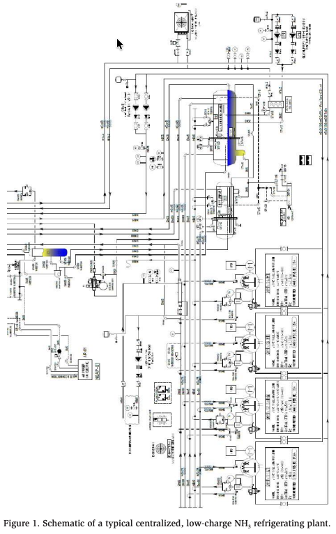
Figure 1 details a typical dual-stage, centralized, low-charge NH3 refrigerating plant with four reciprocating compressors. The evaporative condenser and the field piping, including evaporators, are not shown for clarity. This system services a 31,000 m3 (1,094,755 ft3 ) mixed food service facility. The medium temperature rooms are cooled by a glycol loop as shown. The freezer is serviced by three evaporators all arranged for dry expansion refrigerant feed and hot gas defrost. One compressor has a dualduty function for redundancy. An important feature of the plant design is the total elimination of liquefied refrigerant from the entire suction line network.
During hot gas defrost, the condensate is returned to the intercooler via a highpressure float valve for maximum defrost efficiency. The low-temperature separator protects the first-stage compressors against liquid flood-back. Any liquid trapped in the low-temperature separator is boiled off with a liquid boil-off coil. Warm liquid from the high-temperature segment flows through this boil-off coil. There is no high-pressure receiver. The priority vessel at the condenser outlet expands the liquid into the intercooler, which can accommodate the entire refrigerant inventory. All interconnecting refrigerant pipelines are 304 stainless steel with an absolute internal roughness 20–40 times lower than for carbon steel. The refrigerant inventory is 1.2 kg of NH3 per kW (approximately 9.3 lb. per TR) cooling capacity.
The dry expansion refrigerant feed for the low-temperature evaporators requires the plant designer to pay particular attention to the heat exchanger fundamentals of the evaporators (air coolers). Most performance deficiencies in low-charge NH3 plants originate in the evaporator design, the liquid feed control, and hot gas defrost management, or they are caused by operation outside the optimal evaporator performance envelope. In liquid overfeed applications, it is customary for plant designers to rely on the evaporator design being performed by the evaporator supplier. In dry expansion NH3 applications, this can be a risky approach.
The plant designer must determine the required operating envelope for each evaporator. In practice, this often means designing for relatively high turbulence (refrigerant-side pressure drops) at the high-capacity end of the operating envelope to avoid liquid flood-backs and poor controllability at the lower end of the operating range. Generally, this design approach leads to higher evaporator capital costs than in liquid overfeed plant.
The practical experiences of the author as well as research by Cotter (2008) indicate that the extent to which the internal surfaces of the evaporator (air cooler) tubes are exposed to the boiling NH3 refrigerant is greatly influenced by the thermal conductivity of the tube material and by internal tube surface enhancement (Nelson, 2016). Furthermore, practical experiences also support the employment of gravity distributors as opposed to conventional distributors, particularly in low-temperature evaporators with hot gas defrost.
Energy Efficiencies
The energy efficiencies of a range of centralized, low-charge NH3 refrigerating plants servicing mixed, refrigerated warehouses are illustrated in Figure 2.
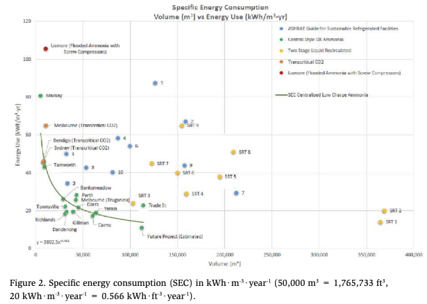
The horizontal axis represents refrigerated volume, the vertical axis Specific Energy Consumption (SEC). The specific energy consumption is calculated by dividing the total annual energy consumption of the refrigerating plant in kWh by the total refrigerated volume of the facility in m³. The values shown are a comparison between a range of centralized, low-charge NH3 plants (green markers), ten conventional North American liquid overfeed systems (blue markers numbered 1–10) (Reindl, 2010,) and a range of conventional, highly energy-optimized, Australian, dualstage liquid overfeed systems with screw compressors (yellow SRT markers). The Australian systems were installed by Scantec between 1999 and 2013 for a major cold storage chain. The red marker at the top represents a flooded NH3 plant with two single-stage, economized screw compressors. The SEC values representing transcritical CO2 systems are signified by orange markers. The values for the Bendigo and Sydney locations represent only the cooler months (i.e., not a full year).
How a low-charge NH3 plant servicing a 27,000 m3 (953,496 ft3 ) mixed food service facility compares in terms of energy efficiency with a range of mixed North American refrigerated warehouses belonging to one major cold storage chain is illustrated by the small green star in the bottom left-hand corner of Figure 3. This star is also included in Figure 4.

The important questions emerging when analyzing Figures 2 and 3 are why is there such a large spread between the SEC values recorded for industrial, dual-stage liquid overfeed plants employing NH3, and screw compressors, and why do the low-charge NH3 systems form what appears to be a more predictable cluster in Figure 2?
There is no single answer to the question as to what causes the spread in SEC values. Some possibilities are:
- The systems are oversized and the SECs recorded reflect how close or how far away from 100% the average operating condition throughout a normal year is – plant oversizing generally causes higher SECs, whereas if the plant operates closer to maximum capacity most of the time, lower SECs are experienced;
- Excessive liquid overfeed ratios – in most large industrial NH3 plants, the amount of refrigerant circulated by the refrigerant pump(s) is not regulated as a function of load; therefore, the overfeed rate increases as the refrigeration load on the plant reduces, potentially causing brining;
- Incorrectly sized wet suction risers, or high abundance of wet suction risers operating at low superficial vapor velocities cause liquid flow reversal;
- Incorrectly circuited evaporators cause discrepancies between actual and optimal evaporator operating envelopes which, for dry expansion feed evaporators, can lead to more severe operational difficulties than for liquid overfeed units (Jensen, 2009);
- Poor overall system part-load performance caused by inappropriate compressor selection/combination, poor capacity control, brining, and/or inadequate employment of variable frequency drives;
- Excessive defrost frequency caused by a combination of narrow fin spacing, poor automation, poor piping practices, and excessive infiltration;
- System contaminants/impurities such as water, non-condensables, oil, scale, and ice;
- Operational/construction matters such as hot product, poor door management, inefficient lighting, poor maintenance, lack of power factor correction, voltage variations, poor insulation, leaking building envelope, poor building layout, poor product storage layout, poor door seals, and the general environmental conditions of the location.
On the other hand, the SEC records for centralized, low-charge NH3 systems represented by the green dots display far less variability than the SEC records for other types of NH3 plants shown in Figure 2. The possible reasons for this are:
- Significantly improved turn-down ratios through elimination of liquid in all suction lines/risers, selection of compressors/compressor combinations with improved part-load performances, optimization of evaporator fan speeds, and extensive use of variable-frequency drives;
- Optimization of all evaporator operating envelopes to reflect actual heat loads on the plant and projected heat load variations within individual refrigerated spaces;
- High-pressure float valve-controlled condensate return to the intercooler during hot gas defrost;
- High-efficiency oil separation on all compressors and dual-stage compression;
- Defrost frequency minimization through application of desiccant driers (dehumidifiers) and relatively wide evaporator fin spacing in freezers ≥10 mm (≤2.5 FPI);
- Reactivation of desiccant driers and provision of subfloor heating via integral heat recovery system(s);
- Office air conditioning using the centralized, low-charge NH3 plant via a glycol loop.
Energy Conservation Potential Through Adoption of Low-charge NH3 Technologies
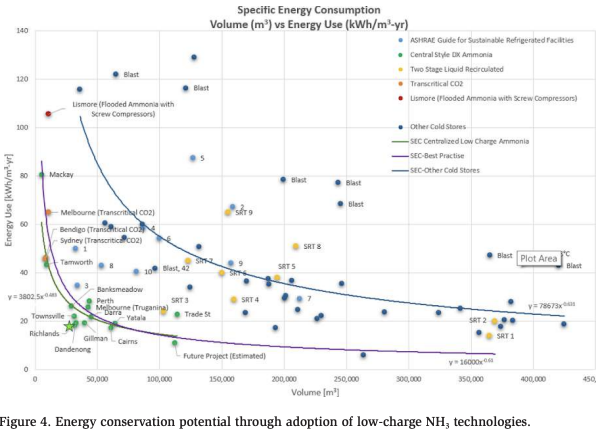
The bright future of low-charge NH3 technologies is underpinned by the very significant energy conservation potential as illustrated in Figure 4. Here, the content of Figure 2 has been expanded to include SEC values from refrigerated warehouses delivering average practice energy performances.
Average practice is represented by the upper graph, which is a result of a polynomial regression analysis that ignores the outliers. The recorded performances of centralized, low-charge NH3 plants are represented by the equation SEC = 16,000* V-0.61 [kWh·m-3·year-1] where V is refrigerated volume [m3 ]. The energy conservation potential is the vertical distance between the upper curve and the curve drawn through the green markers. For a typical 100,000 m3 (3,531,467 ft3 ) mixed refrigerated warehouse, the energy conservation potential is a factor of approximately 4 or 75%. Unsurprisingly, this level of energy conservation potential is considered by many refrigerated warehouse operators to be unrealistic and not believable. However, the performance records, which are simply annual kWh meter readings divided by refrigerated volumes, are factual. What is not known is the extent to which operational and environmental variables have influenced the individual results shown. Despite this uncertainty, the energy performance records show a clear trend. Centralized, low-charge NH3 plant, as described here, displays a significant capacity for energy efficiency improvement compared with liquid overfeed in cold storage applications and beyond.
Energy Performance Penalty Associated with Liquid Overfeed
In large, expansive liquid overfeed systems with significant load variations (or significant oversizing) causing flow reversal in wet risers throughout the plant, the energy performance penalty associated with liquid overfeed cannot be modeled readily. Modeling may be possible using computational fluid dynamics (CFD); however, this technique remains unexplored for this application. There are presently no correlations available for realistic prediction of wet riser pressure drops during flow reversal, meaning that the energy performance penalty associated with liquid overfeed can only be quantified experimentally. Such an experiment requires an energy performance comparison between two conceptually identical refrigerating plants performing identical functions where the only technical difference is the refrigerant feed method—liquid overfeed versus dry expansion.
An opportunity for such a comparison emerged in 2018 when a centralized, lowcharge NH3 plant servicing a mixed 44,000 m3 (1,553,845 ft3 ) transport facility was commissioned in Brisbane, Australia. The new facility replaced a 22,000 m3 (776,923 ft3 ) facility commissioned in 2010. Both facilities are serviced by conceptually identical refrigerating plants as described in Figure 1 but without the glycol loop. In the case of the older facility, the refrigerant feed is liquid recirculation. In the newer facility, the refrigerant feed is dry expansion. Both facilities undertake the same activities, are located in the same geographical area, are owned by the same entity, and were designed by the same refrigeration consultant/superintendent.
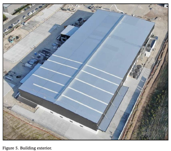
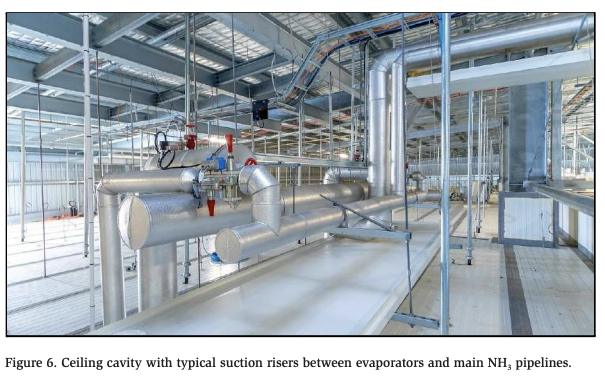
The specific energy consumption of the older system with liquid overfeed is 1.4 times the value SEC = 16,000*V-0.61 in Figure 4, whereas the newer system has a specific energy consumption that is 0.97 times that value. Therefore, the energy performance penalty associated with liquid overfeed in this case is estimated at (1 – 0.97/1.4) * 100 ≈ 30%. The facilities are typical single-level buildings with ceiling suspended evaporators and refrigerant pipelines and valve stations situated in the ceiling cavity. Figures 5 and 6 show the building exterior and the ceiling cavity of the newer facility, respectively, with the suction risers that are typical of many of these types of installations.
Of course, the “experiment” described does not match a laboratory situation where more variables influencing energy consumption may be captured and where all the differences between liquid overfeed and dry expansion may be isolated with greater certainty. However, even in a laboratory setting it would be difficult to expose both plants to identical loading patterns throughout a year and isolate the system design differences such as evaporator surface areas, evaporator design, and evaporator defrost control that are inherently different between low-charge and liquid overfeed systems. In this comparison, at least the influences of compressor types, compressor numbers, and compressor sequencing are eliminated because these are identical in both cases.
If the energy performance penalty associated with liquid overfeed is indeed around 30% as calculated here, or between 18% and 38% as estimated by Watters and Nelson (2017), then this represents a significant challenge to the global industrial ammonia refrigeration industry to improve its performance. Ever since the commercialization of CO2 refrigerating plants (both subcritical and transcritical) started around 20 years ago with multiple smaller reciprocating compressors, evidence has been mounting that the traditional design methodologies used in largescale ammonia refrigerating plants may not deliver optimal energy performance. The emergence of centralized, low-charge NH3 plant that also utilized multiple reciprocating compressors and further sought to take full advantage of the superior thermodynamic and transport properties of ammonia, has contributed further to the body of evidence that the ammonia refrigeration industry needs to change its practices with respect to energy efficiency.
The NH3 refrigeration industry faces technical and commercial challenges from promoters of CO2–based technologies. The challengers frequently claim lower capital costs, improved safety, and reduced maintenance costs compared with NH3. Claims of higher energy efficiency than equivalent NH3 refrigerating plant are often met with indignation by highly experienced NH3 practitioners, who may possess significant expertise in the employment of the refrigerant capable of delivering the highest cycle efficiencies of all but fail to recognize what Figures 3 and 4 clearly show—namely, that current plant designs often prevent NH3 from performing to its potential.
This may well be an inconvenient truth that strikes at the very core of many ammonia refrigeration practitioners’ careers. However, if the emergence of new knowledge challenges the status quo, then so be it. The ammonia refrigeration industry must embrace this new knowledge and act on it in the interests of long-term survival and the community at large.
Demonstrated Advantages of Low-charge NH3 That Can Support Business Cases
The low-charge NH3 technologies described herein are commercially justifiable for mixed refrigerated warehouses with refrigerated volumes that exceed approximately 10,000 m3 (353,147 ft3 ). Centralized, low-charge NH3 plants servicing smaller facilities have been implemented (Jensen, 2019), but the smaller the facility, the longer it takes to return the capital cost difference between low-charge NH3 refrigerating plants and other competing solutions such as transcritical CO2. Based on prevailing Australian unit energy costs, the tipping point is around 10,000 m3 (353,147 ft3 ) mixed storage volume. For smaller plants, the energy savings deliver internal rates of return that are considered inadequate by seasoned investors. Therefore, investment in centralized, low-charge NH3 plants must either be incentivized for smaller facilities or that segment left to other technologies.
Although the focus of this paper is energy and energy savings, numerous factors influence business decisions. For example, there are local councils in Australia that impose stricter development approval procedures when NH3 inventories in refrigerating plants exceed 100 kg (approximately 220 lb.). Many businesses prefer alternatives to NH3 as a matter of company policy. Strategy, capital, human resources, technology, and emotion are other factors that may take priority over energy cost reductions.
The first case is an existing conventional refrigerating plant with single-stage compression comprising two economized screw compressors in parallel servicing a small, mixed food service facility with a refrigerated volume of approximately 10,000 m3 (353,147 ft3 ). The specific energy consumption of the existing system is represented by the red marker in Figure 2, although the introduction of floating condensing pressure after the plant was originally commissioned in 2012 reduced SEC to around 80 kWh·m-3·year-1 (2.27 kWh·ft-3·year-1).
The annual operating costs for the existing system in 2020 were approximately AUD 230,000 for energy and AUD 150,000 for maintenance. The energy costs have been largely unchanged since plant commissioning in 2012, but maintenance costs have been escalating. At the time the plant owner decided on complete plant replacement, total annual operating costs were approximately AUD 380,000.
The owner also owns and operates an almost identical facility about 400 km further south of the first plant. This second plant is serviced by a centralized, low-charge NH3 plant, also commissioned in 2012. The plant is, in principle, designed as described in Figure 1, but without a glycol loop. The specific energy consumption of this low-charge NH3 plant is included in Figure 2 and is referenced as “Tamworth.”
The plant owner, therefore, has reliable records of operating expenses available for both plant concepts dating back to the year of the original commissioning in 2012. The difference in annual operating costs between the plants was recorded at approximately AUD 260,000 in 2020. Based on the capital cost of the replacement system of a little over AUD 1.2 million, complete replacement will deliver a simple pay-back period of around 4.5 to 5 years. This pay-back period is calculated based on operating cost reductions. The new plant is anticipated to be commissioned during the first quarter of 2022. The plant owner’s decision was in this case not based on the return estimated above, which was merely considered a bonus. The deciding factors were staff retention and the fact that a completely new plant could be installed and commissioned without interruptions to the business. Frequent after-hours plant faults had resulted in three plant managers resigning within nine years.
The greater the refrigerated volumes of facilities, the shorter the simple pay-back period tends to be for identical unit energy costs, begging the question as to why complete replacements are not carried out more frequently. The answer is that it is difficult to convince most owners of refrigerating plants to part company with what appears to be a well-functioning, relatively reliable system that has provided good service for several years. Many energy-inefficient systems remain in service for many years and replacement often does not occur until the end of life. When they are ultimately replaced, there is no guarantee that they will be replaced with a system compliant with best-practice energy performance benchmarking, simply because such benchmarking is non-existent in most polities.
The second case concerns a major refrigerated warehouse operator in Melbourne, Australia, who decided in 2019 to consolidate three existing refrigerated warehouses into one new refrigerated distribution facility serviced by a centralized, low-charge NH3 refrigerating plant. The combined annual electricity cost of the three existing warehouses was around AUD 750,000 in 2018/19. This cost reflects the energy consumption associated with batch blast freezing approximately 300 metric tons (approximately 660,000 lb.) per week.
The new facility has a refrigerated volume of approximately 60,000 m3 (2,118,880 ft3 ). Blast freezing is carried out in in-rack blast freezers. The air circulation within the freezer space is based on the cold lake air distribution principle. The defrost method is automatic ambient air defrost. The evaporators are of the insulated cooler type installed outside the refrigerated
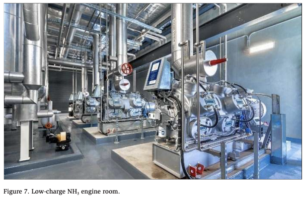
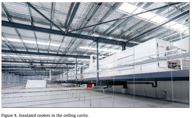
spaces. These feature automatic air-side isolation from the freezers in the event of refrigerant leaks. The total NH3 inventory is 472 kg (1,038 lb.). This represents 0.66 kg per kW (5.1 lb. per TR) total refrigeration capacity. The total operating NH3 inventory within all the evaporators is 25 kg (55 lb.). Figures 7 and 8 show the engine room and the insulated cooler arrangement, respectively.
The projected reduction in annual energy consumption costs was approximately AUD 250,000 the first month after commissioning. Further reductions up to around AUD 400,000 per annum are anticipated for 2022. The projected additional energy use reductions are the results of retrofitting variable frequency drives to the blast freezer fans and of the warehouse subsoil temperatures approaching a steady-state condition.
This installation is a typical example of the significant reductions in energy consumption that are achievable through the general modernization of mixed refrigerated warehouses. Average practice for a 60,000 m3 (2,118,880 ft3 ) warehouse without blast freezing would, according to Figure 4, have delivered SEC values around 60 kWh·m-3·year-1 (1.7 kWh·ft-3·year-1). The new facility achieves around a third of this. In this case, the average unit electricity cost was recorded at AUD 188.8 per MWh during the 2018/19 financial year. A reduction in SEC from 60 to 20 kWh·m-3·year-1 (from 1.7 to 0.57 kWh·ft-3·year-1) represents around AUD 450,000 per year. At a plant capital cost of approximately AUD 3,000,000, the refrigerating plant capital outlay will therefore be returned in full well before the expiry of a typical fifteen-year lease period.
In a typical developer/consultant/tenant/construction company/refrigeration contractor scenario in Australia (and possibly elsewhere) there is little to no focus on energy consumption minimization for mixed refrigerated warehousing facilities. Firstly, there is no best-practice energy performance benchmark requiring either voluntary or mandatory compliance. Therefore, stakeholders are unable to define what “energy efficiency,” “sustainability” and “green” represent in terms of actual deliverables. Secondly, the developer has a clear desire to minimize capital costs. This defines the key performance indicators for construction companies charged with project delivery and sets the scene for what refrigeration contractors must do to be successful. Thirdly, the tenant, who is usually a logistics expert, ordinarily has limited to no influence on refrigerating plant procurement decisions even though the responsibility for energy and maintenance costs normally rests with the building occupant for the duration of the lease.
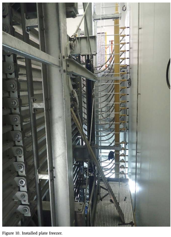
The third case relates to meat freezing. Around 80% of the frozen beef production in Australia and New Zealand is processed in large-scale plate freezer installations such as the example shown in Figures 9 and 10. The plate freezer in Figure 9 is one of four, each with a unit capacity of around 1750 standard 27.2 kg (60 lb.) meat cartons.
A low-charge NH3 freezer plate covered by AU Patent 2013202295 issued to Colmac Coil Manufacturing, Inc. now enables very significant reductions of the refrigerant inventory of these typical large-scale plate freezer installations, by a factor of around 30 to 40.

The fourth example is a small-stock abattoir in South Australia serviced by a centralized, low-charge NH3 plant. The facility includes carcass chillers, blast freezers, a processing room, and a freezer store. Refrigerant feed control, employing a combination of superheat and refrigerant quality control signals, enables entering temperature differences between refrigerant and air at the evaporator inlets down to 2.5–3°K (4.5–5.4°F). This is useful for blast freezer design to ensure relatively high levels of energy efficiency. The facility was previously serviced by stand-alone, HFC-based, air-cooled systems. Following the decision to expand, the owner had to consider either continuing with HFC-based unitary equipment or implementing an expandable, centralized low-charge NH3 concept. The energy consumption for a full year’s operation will be available by the fourth quarter of 2022.
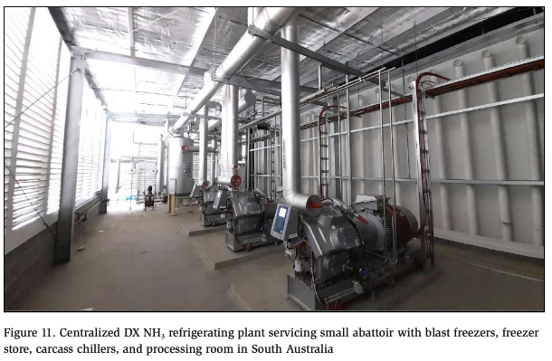
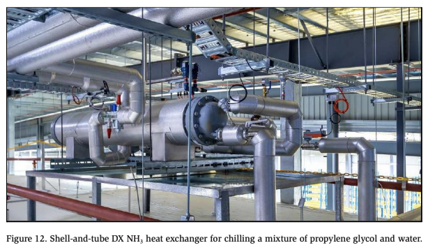
Figure 12 shows a small shell-and-tube type, dry expansion liquid chiller mounted in the ceiling cavity of a food service facility. The facility is refrigerated by a centralized, low-charge NH3 refrigerating plant, but one small room within this facility is of an occupancy classification requiring the use of a secondary refrigerant for compliance with AS/NZS 5149. The shell and tube glycol/NH3 heat exchanger is installed directly above the room in question and connected to the central subcooled liquid supply and medium temperature dry suction.
In May 2020, a dual-stage, three-temperature, centralized, low-charge NH3 refrigerating plant was commissioned in northern Germany. The plant is shown in Figure 13.
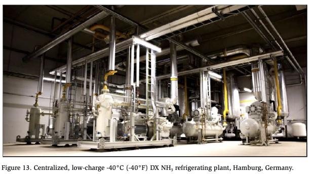
The plant services a refrigerated distribution facility with a combination of freezer and chiller rooms as well as three low-temperature batch blast freezers operating at evaporating temperatures of around -40°C (-40°F) and air temperatures of around -32 to -35°C (-25.6 to -31°F). The plant comprises a combination of screw compressors and reciprocating compressors. There are two screw compressors for the -30°C (-22°F) temperature level, two screw compressors for the -40°C (-40°F) level, and three reciprocating machines for the -10°C (14°F) second compression stage temperature level.
There is no technical reason why low-charge NH3 technologies cannot be used for medium- and large-scale low-temperature in-line chilling and freezing systems for pig carcasses, vegetables, processed foods, and the like. The 30–50 times lower operating refrigerant inventories in the low-charge evaporators employed within these systems greatly reduce pump-out and defrost times, making it much easier to accommodate the very compressed defrost time intervals characteristic of many of these applications with automatic, sequential defrost during production hours. The evaporators of these processing systems are often fitted with 3 to 5 m (9.8 to 16.4 ft) tall suction risers. Elimination of liquefied, relatively heavy refrigerant from these risers will deliver significant energy performance improvements, as discussed above.
The capital costs of centralized, low-charge NH3 refrigerating plants as described herein are up to 10% more capital-intensive than equivalent liquid overfeed systems. The more evaporators a system contains, the greater is the additional capital cost compared with equivalent liquid overfeed concepts. The two main reasons for this are 1) additional evaporator capital costs and 2) additional automation costs. Within centralized, low-charge NH3 plant, there is a tendency for designers, as well as users, to include/demand more information on the display of the Supervisory Control and Data Acquisition (SCADA) system than perhaps would have been included for a conventional liquid overfeed system, presumably because there is more information available within the control system. Of course, this will influence programming time, the costs of electronics and, hence, capital costs.
Based on the practical experiences outlined herein, there is no doubt that the relatively minor additional capital costs associated with centralized, low-charge NH3 refrigerating plants provide very attractive returns in the form of energy costs savings. Simple pay-back periods of 12 months to 2 years for the differential capital costs between centralized, low-charge NH3 plant and conventional liquid overfeed concepts are common.
Conclusion
The global ammonia refrigeration industry needs to change. Up until the commercialization of CO2-based refrigerating plants started accelerating around two decades ago, ammonia had enjoyed a unique and almost unchallenged position as the refrigerant of choice for large, expansive industrial refrigeration installations. Although it is unlikely that this will change in the foreseeable future, the ammonia refrigeration industry is and will continue to be under pressure to become even safer and much more energy-efficient than it is today. Not only will this translate into reduced refrigerant inventories, but it will also increase implementation costs as well as ongoing compliance costs—in some jurisdictions more than others. Without wholesale industry adaptation to the latest NH3 technologies, the issues highlighted will slowly erode the competitiveness and market share of ammonia refrigerating plants compared with competing technologies that are not subject to the same constraints.
If the ammonia refrigeration industry does not change, competing solutions will challenge centralized, low-charge NH3 plants in the medium capacity range. A considerable portion of this market segment presently employs refrigerants destined for phase-down under the Kigali Amendment to the Montreal Protocol. Over time, it will be necessary for this segment to change refrigerants. There are several options available for stakeholders to choose from that are either interim in nature (HFC/HFObased) or completely future-proof (natural refrigerants). The choice for end-users is not easy because marketing efforts are fierce and credible technical information not readily accessible for laypersons charged with the responsibility of making technically challenging procurement/business decisions.
One of the types of operations within the medium capacity market segment is mixed refrigerated warehouses with refrigerated volumes ranging from ~10,000 to ~100,000 m3 (353,147 to 3,531,467 ft3 ). These facilities typically have total refrigeration capacities ranging from around 100 kW (28.5 TR) to approximately 600 kW (170.9 TR) for refrigerated storage and distribution only (no blast freezing). Centralized, low-charge NH3 refrigerating plants are an excellent and very futureproof match for this market segment, which could also include some supermarkets. The most stringent best-practice energy performance benchmarks are well within reach by adopting low-charge NH3 technologies for this and other similar applications. In addition, ammonia inventories below 500 kg (approximately 1,100 lb.) are easily achievable for the capacity range used as an example above.
Alternative, future-proof solutions for the medium capacity market segment typically employ CO2 refrigerant. This refrigerant is unable to compete in terms of energy efficiency, simplicity, and longevity with well-designed centralized low-charge NH3 refrigerating plants as described herein. However, CO2-based refrigerating plant concepts can certainly compete in other areas such as refrigerant toxicity, space requirements, operating weights, regulatory compliance simplicity, and capital costs.
Significant opportunities also exist in the retrofit market, represented by large-scale ammonia refrigeration plants that have been built to the liquid overfeed design principles that have evolved from the 1960s to the present day. Typical features of such plants are overfeed ratios that are not controlled and/or are excessive, incorrectly sized wet risers, extensive part-load operation, oil fouling, excessive water content in the refrigerant, and poor compressor sequencing. Implementation of technologies related to low-charge NH3 plant, such as replacement evaporators with modern feed control, oil separation upgrades, new SCADA systems, implementation of variable frequency drives, and integration of compressors with improved part-load efficiencies, may achieve significant energy efficiency improvements and attractive returns without replacing the entire plant.
For low-charge NH3 technologies to achieve justified prominence will take the combined efforts of all stakeholders. Adopting such technologies will not only benefit practitioners within the global ammonia refrigeration industry, but it will also benefit the wider community in the form of reduced emissions and a higher probability that natural refrigerant-based technologies will leapfrog less-efficient interim solutions based on synthetic refrigerants.
References
Briley, George, C. 2004. ASHRAE Journal, 46(9):48–50.
Cotter, D.J., Missenden, J.F., Maidment, G.G. 2008. “An Experimental Investigation of Two Phase Ammonia in Tubes and Bends.” Proc. IIF/IIR Conference on Applications for Natural Refrigerants, Copenhagen, Denmark, 436–443.
Jensen, S.S. 2009. “Extended Surface Air Coolers for Industrial Plants – the Contractors Perspective.” Proc. IIAR Conference and Exhibition, Dallas, Texas, U.S.A.
Jensen, S.S. 2019. “Real Energy Efficiency of DX NH3 versus HFC.” Proc. IIF/IIR International Congress of Refrigeration (ICR), Montreal, Canada, Manuscript ID: 466, DOI: 10.18462/iir.icr.2019.466.
Marcinichen, J.B., Thome, J.R. 2019. “Prediction of Void Fraction and Pressure Drops in Vertical Ammonia Risers.” Proc. 2019 Natural Refrigerants Conference and Expo, Phoenix, Arizona, U.S.A., T479.
Nelson, B.I., 2016. “DX Ammonia Piping Handbook, 3rd Edition.” Colmac Coil Manufacturing Inc.
Nelson, B.I., Watters, R. “Low-charge ADX Ammonia.” Proc. Global Cold Chain Expo, June 13–15, Chicago, Illinois, U.S.A.
Nitschke, T., Jensen, S.S. 2019. “Thermodynamic Modelling of Liquid Overfeed and Dry Expansion Feed Central NH3 Refrigeration Plants to Determine Differences in Energy Performance.” Proc. 8th IIF/IIR Conference: Ammonia and CO2 Refrigeration Technologies, Ohrid, North Macedonia, Manuscript ID: DOI: 10.18462/iir.nh3- co2.2019.0008, 66–73.
Reindl, D.T., Jekel, T.B. 2010. “Industrial Refrigeration Energy Efficiency Guidebook.” Industrial Refrigeration Consortium, University of Wisconsin–Madison, 1513 University Avenue, Madison, Wisconsin 53706, U.S.A., 260 pages.
