2022 Technical Paper #2
Proper Installation and Maintenance Practices for Variable Frequency Drives
Author:
Paul Jasczynski, Sales Marketing Manager, Logic Technologies
Abstract
The use of a variable frequency drive (VFD) to control the speed of an AC induction motor has numerous benefits, including energy savings, improved reliability, reduced equipment wear and tear, and more precise control of motor speed.
When operating, VFDs generate heat, and the output voltage waveform is not a true, clean sinewave. These characteristics present challenges when installing a VFD. However, following a few proper installation practices can help ensure successful operation. Most VFDs fail because of an improper installation and not because of a poor-quality product.
The following seven recommended practices will help ensure a successful VFD installation and optimal equipment life.
1. Install Input Line Reactors
VFDs generate electrical “noise” and harmonics, which typically migrate back up the incoming line. Electrical noise is defined as undesirable electrical signals that distort or interfere with the desired electrical signal. These interferences can be caused by lightning strikes, solid-state converters such as VFDs, fluorescent lighting tubes, welding equipment, or even imperfect design or installation of the circuit itself.
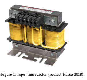
This electrical noise can affect other electronic devices. An input line reactor (Figure 1) helps eliminate this noise by acting as a current-limiting device, filtering the waveform and attenuating electrical noise and transients associated with the system.
As the name implies, line reactors are typically installed on the line side of a VFD. Harmonic compensated line reactors are specially designed to handle the waveform’s harmonic content. By inserting inductive reactance into the circuit, which is a high impedance to harmonic frequencies, line reactors reduce the harmonics produced by a VFD system
The impedance of an input line reactor will help soften and slow down any incoming voltage disturbances (spikes and surges) that might damage the drive (Figure 2). Also, the incoming current waveform is stabilized, which in turn reduces the harmonic current drawn from the VFD’s power system.
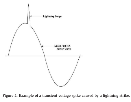
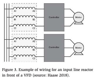
Any number of factors can cause voltage spikes: short circuits, lightning strikes, power outages, circuit breakers tripping, etc. Installing an input line reactor in front of the VFD can help eliminate this problem (Figure 3 ).
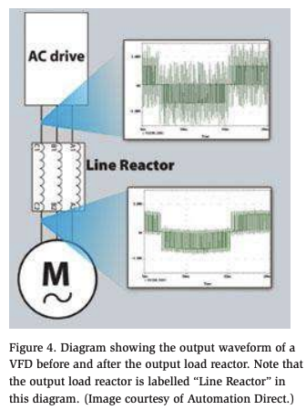
2. Install an Output Load Reactor on the Load Side of the VFD with Motor Lead Lengths Greater than 100 ft
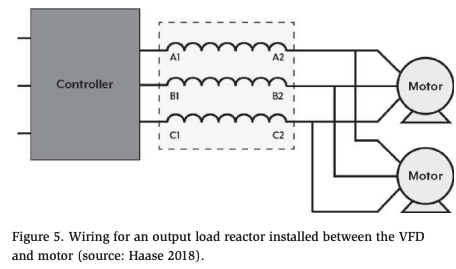
A VFD generates voltage disturbances that are transmitted down the line and reflected back from the motor (Figure 4). These pulses can cause significant damage to the motor, VFD, and motor cable. An output load reactor will mitigate or eliminate these voltage pulses (Figure 4), which results in less stress on the motor and motor cable. Output load reactors are simple to install and go on the output side of the VFD (Figure 5). These devices incur a minimal cost with a potentially high return on investment in terms of avoided damage and repairs.
3. Install Shielded VFD Cable from the VFD to the Motor
Shielded VFD cable should be the only cable used to wire a VFD. It has numerous advantages over standard THNN (thermoplastic, high heat-resistant, nylon coated)- type cabling insulation:
- VFD cabling is rugged. It does not have to be placed in a metal conduit, thereby saving installation costs.
- VFD cable has XLPE (cross-linked polyethylene) insulation, which resists high temperatures. THHN cabling insulation generally comprises a thermoplastic-type material that can break down or melt at high temperatures.
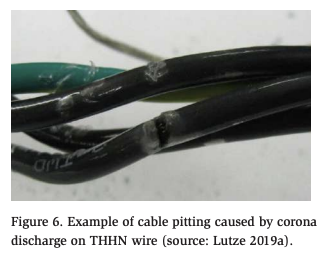
- The XLPE insulation also provides low capacitance for increased motor life, reduced possibility of corona discharge, and reduced magnitude of standing waves. Corona discharge is simply an electrical discharge. The corona inception voltage (CIV) is the voltage required to initiate a visible corona discharge from a conductor. Once the CIV is reached , corona discharge will occur, and that discharge will affect the insulation. As corona discharge produces heat, this discharge melts thermoplastic insulations (like the PVC insulation used in THHN cables). Melted insulation works poorly, and cables with melted insulation will experience a short circuit when voltage breakdown occurs in the area of damage. THHN insulation typically has high capacitance that can lead to cable charging, which in turn can break down the THHN insulation and cause corona discharge or complete cable failure (Figure 6).
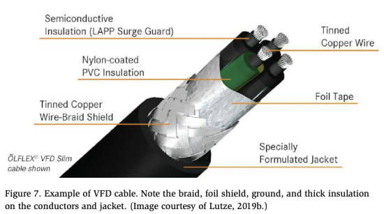
- VFD cable has shielding to protect against low-frequency and high-frequency noise. The output waveform of the VFD generates high-frequency pulses that can wreak havoc on other equipment. In addition to a ground wire, VFD cabling will also have a foil and/or wire-braid shield (Figure 7).
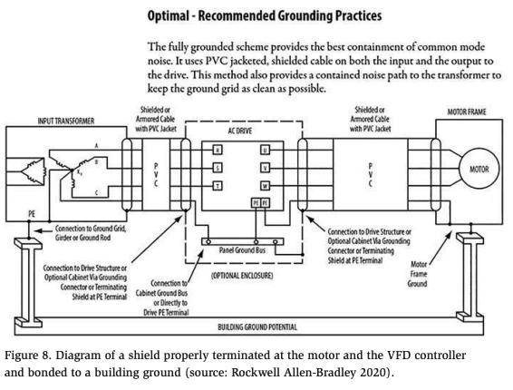
- To remove the electrical noise from the system, the shield and cable ground must be properly terminated at both the motor and the VFD (Figure 8). The motor and VFD must be grounded together along with the braid and shield. The grounding cable then needs to be connected to an earth ground (typically the building structure). A panel ground or metal conduit ground connection will not provide an optimal connection.
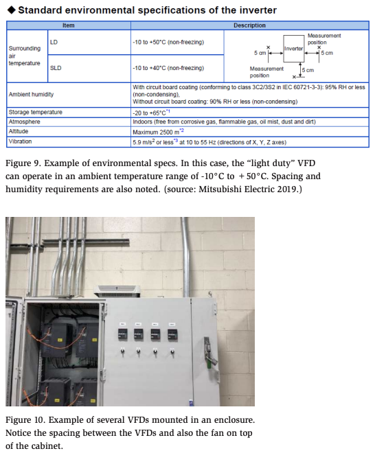
4. Verify/Check the VFD’s Normal Operating Temperature
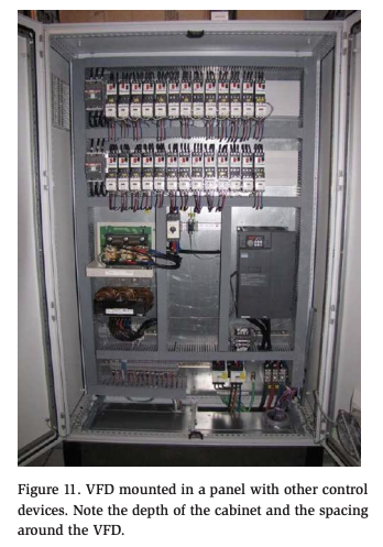
All VFDs generate heat and have a normal operating temperature range. All VFDs need adequate air flow and cooling. Most manufacturers publish these data in the user manual (Figure 9). End users must also consider the environment in which the VFD will operate: Will it be exposed to dust or dirt? Might it come into contact with water? Could excessive vibration affect it? For these reasons, most VFDs are mounted in enclosures, but because a VFD generates heat, the end user or installation specialist may wish to perform a heat-rise calculation to determine if additional cooling is required (ventilation fans, air-conditioning units, vortex coolers, etc.; Figures 10 and 11).
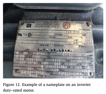
5. Use Inverter Duty–Rated Motors
Inverter duty–rated motors are designed to be used with VFDs (Figure 12). They can withstand the higher voltage spikes that VFDs produce (this is amplified at longer cable lengths) and can run at very slow speeds without overheating.
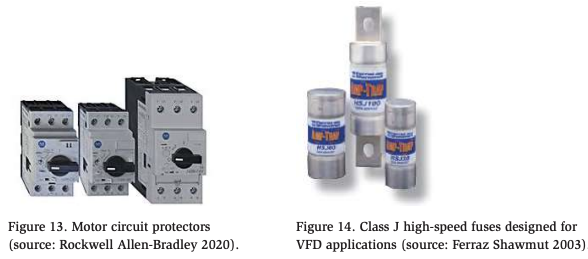
6. Install Protective Devices in Front of the VFD
Installing motor circuit protectors (MCPs) or high-speed fuses (High Speed Class J) in front of the VFD is also good practice. These devices will protect the VFD in the event of a short circuit and will also meet the National Electrical Code requirements for branch circuit protection. These small and relatively low-cost devices will not only protect sensitive equipment, they will also protect employees who have to work on the equipment. An MCP will provide short circuit and overload protection and provide a means for de-energizing the system (Figure 13). Fuses are small in size and can quickly open upon a detection of a short circuit or overload condition (Figure 14).
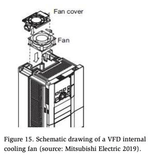
7. Perform an Annual “Health Check” on VFDs
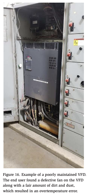
A yearly check of the VFD installation is highly recommended. Check the cooling fan on the drive and clean or replace if needed (Figure 15). Check all wires and motor terminations to make sure they are tight. Check the VFD shielded cable for nicks or wear (Figure 16).
Conclusions
The preceding recommended practices represent a practical approach to VFD installation and maintenance that will help prevent premature failure. Nevertheless, end users are encouraged to follow the VFD manufacturer’s installation recommendations, integrating these recommendations as part of a “good practices” program for installing and maintaining VFDs.
In addition, end users are also encouraged to maintain a working partnership with a trusted VFD supplier. A supplier can often provide training, troubleshooting, engineering expertise, and parts to help ensure a successful installation. In the case of a facility lacking the resources to maintain VFDs, another good practice is to outsource the service to a reputable contractor who can provide these services for a reasonable fee.
And finally, end users should never purchase a VFD over the Internet or through a third-party vendor. Although these distributors may offer economy pricing, they are often unable to provide the necessary services to support their products.
References
Ferraz Shawmut. (2003). “High-speed class J fuses.” Document HSJ2003 Q10000. Available at https://ferrazshawmutsales.com/pdfs/HSJ6PgBrofinal.pdf. Gross Automation, Brookfield, WI.
Haase, J. (2018). “Line and load reactors basics.” TCI Tech Paper. Available at https:// transcoil.com/wp-content/uploads/2018/02/reactor-benefits-tech-paper.pdf. TCI, Germantown, WI.
Lutze. (2016). “Can you afford downtime or safety hazards?” Available at https:// smithautomation.com/wp-content/uploads/2016/10/LUTZE-Driveflex-XLPE_vs_ THHN.pdf. Lutze, Inc., Charlotte, NC.
Lutze. (2019a). “Shield termination guide for Lutze VFD cables.” Available at https:// www.lutze.com/downloads/file/shield-termination-guide-for-lutze-vfd-cables/. Lutze, Inc., Charlotte, NC.
Lutze. (2019b). “Drive FAQs.” Available at https://www.driveflex.com/about-vfds/ faq/. Lutze, Inc., Charlotte, NC.
Mitsubishi Electric. (2019). “Inverter—F800 instruction manual (detailed).” Document IB(NA)-0600547ENG-C(1803)MEE. Available at https://www.manualslib. com/manual/1409691/Mitsubishi-Electric-Fr-F820-00046.html?page=1#manual. Mitsubishi Electric, Tokyo.
Rockwell Allen-Bradley. (2020). “140M motor circuit protectors.” Available at https:// ab.rockwellautomation.com/Circuit-and-Load-Protection/Motor-Protection/140MMotor-Circuit-Protectors. Rockwell Automation, Milwaukee, WI.
Shumen, B. (2013). “Choosing the right cable for your variable frequency drive (VFD) system.” Available at https://www.belden.com/hubfs/resources/knowledge/ white-papers/choosing-right-cable-for-vfd-system.pdf. Belden, St. Louis, MO.
Wetzel, S. (2019). “VFD cables—a safe bet.” Application Note 2012 3/27/2019. Available at http://industrial.southwire.com/en/techblog/2019/04/01/vfd-cables-safebet/. Southwire Company, Carrolton, GA.
Wikipedia. “Voltage spike.” Available at https://en.wikipedia.org/wiki/Voltage_spike.
Acknowledgments
The author would like to thank the following individuals for their contributions to this manuscript:
- Joe Mula, Senior Product Specialist, Mitsubishi Electronics;
- Kaitie Patrick, Wire and Cable Specialist, McNaughton-McKay Electric Company;
- Lauren Schuster, Executive Assistant/Technical Writer, LOGIC Technologies, Inc.; and
- Bruce Karjala, VFD Specialist, McNaughton-McKay Electric Company