2022 Technical Paper #5
Oil Management Design Considerations for Industrial Transcritical CO2 Systems
Author:
Alessandro Silva, Senior Application Engineer, BITZER US
Joe Sanchez, VP Engineering, BITZER US
Abstract
Carbon dioxide as a refrigerant is becoming increasingly more popular on a global scale. The industrial refrigeration market is also finding applications for transcritical CO2 systems. Unlike ammonia systems, oil in CO2 systems is typically miscible and can create unique challenges in its management.
With thousands of commercial transcritical systems running worldwide, much knowledge and experience has been gained on this topic. Certainly these systems can be employed in many industrial environments. However, some industrial systems have increased complexities; not just larger capacities, but also longer pipe runs and/or more dramatic load shifts. These factors should drive an industrial transcritical CO2 system designer to consider additional measures.
In this paper, we first explore a comparison to commercial systems as the baseline of tried-and-true oil management. We then explain some of the unique challenges that an industrial system might find and offer potential solutions as to how to solve them. In addition, the selection of sizing and the components here discussed is paramount to ensure proper compressor lubrication and maintain high levels of heat transfer and efficiency while removing as much oil as possible from the refrigerant. Finally, we provide examples of industrial transcritical CO2 applications such as ice rinks and a food processing plant, where we evaluate and discuss the oil management systems employed in detail.
Introduction
Over the last two decades, commercial transcritical (TC) carbon dioxide (CO2) systems have proven completely viable and sustainable with thousands of systems running worldwide. One key consideration when transitioning this technology to the industrial world is how to manage the oil. Consequently, this paper focuses on important information regarding the planning and execution of oil management systems with practical details obtained from existing systems operating optimally in the field.
In industrial applications, oil return may involve both dry (or direct) expansion (DX) and flooded evaporators. One of the more difficult challenges is to return oil from the flooded evaporators and recirculation tanks back to the compressors. Because a large part of the oil mixes with the CO2 liquid to form an oil-rich concentration, the oil will need to be removed with a proper oil recovery system.
This paper will review various oil management systems for different types of transcritical CO2 systems starting with the most common which are in the commercial refrigeration sector. In addition, there will be an overview of existing industrial-style solutions with suggested improvements that can create a more robust oil management system.
A Look at the Light-Commercial World
No Oil Separator?
Some commercial CO2 refrigeration systems for supermarket applications work without traditional oil separation. In such designs, the oil management system does not require an oil separator and the associated components. The units consist instead of suction headers specially designed to match the size and capacity of the system, and fitted with an oil pick-up mechanism necessary to provide dynamic oil distribution. The main component of the units is a multifunctional vessel known as the “suction receiver,” which also serves as the oil receiver, oil cooler, and where required, liquid separator.
These units allow the compressor suction lines to enter the suction receiver on the topside. The suction receiver utilizes oil pick-up devices for every suction line connected between the suction header and each compressor. In this pick-up mechanism, a venturi tube provides oil flow through each of the suction lines in response to the flow of refrigerant gas. Suction receivers are installed on the lowpressure side of single-stage parallel compressor racks and at interstage pressure of a booster system.
This non-oil separation system design works well for a smaller, fixed store format where requirements and systems are more repeatable. It requires a careful approach, with most systems in the field today based on lab testing, years of experience, and design iterations.
In general, larger custom systems, especially those using parallel compression or ejector technology, require more sophisticated control of the oil management.
Single-Stage Systems with Oil Management
Although TC CO2 compressors are often coupled with low temp (LT) compressors in two-stage systems, there are many medium temp (MT), single-stage systems as well. For example, a variety of TC CO2 packaged chillers and heat pumps with capacities of 50-150 tons of refrigeration (TR) are available in applications such as hotels, data centers, and food processing industries.
These systems are designed with one compressor or multiple compressors in parallel to match the load requirements. In addition, the low side of the system may employ a direct expansion (DX) evaporator or a flooded evaporator. Systems with DX evaporators have a simpler oil management system in comparison to flooded, which will be covered in greater detail later in the paper. (Note: In this paper, DX evaporators are assumed to be connected directly to the compressor suction group as opposed to the use of a suction accumulator or trap with an associated oil pot.)
Single Compressor with DX Evaporator
These units are relatively compact as all components are assembled close to each other (compressors, evaporators, gas coolers, heat exchangers, controls, etc.). Compact CO2 chillers could be designed without an oil separator as discussed in the previous section.
Oil will, of course, still carry over beyond the compressor and move through the system to the evaporator. With a DX evaporator, the compressor suction piping is connected directly to the outlet of the evaporator which enables oil droplets to be carried by the refrigerant and metered back to the compressor. A suction accumulator (between evaporator and compressor) may be used to assist the oil metering in addition to liquid transient protection.
Getting Bigger (More Commercial)
Multiple Compressors in Parallel
An “active” oil system is required when using multiple compressors in parallel on a suction group. The reason is that as compressors cycle on and off to match the system loads, the oil levels of the compressors will fluctuate. Without an active oil management system, one compressor may end up with too much oil and another with too little.
In this setup, a common oil separator and reservoir hold oil and actively deliver the oil to each compressor based on individualized oil sensors and solenoid valves. Electronic oil level controllers have also been used successfully to deal with the higher operating differential pressures normally found in TC CO2 systems.
High-Pressure vs. Low-Pressure Active Oil Management
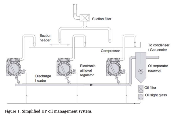
An example of a high-pressure (HP) oil management system is a compressor rack equipped with a combination oil separator and reservoir that is fitted at the discharge side of the TC compressors. There is no float valve in the oil separator reservoir. The oil is at discharge pressure and feeds directly to the electronic oil level controllers installed on the compressor crankcases. An additional level sensor inside the oil separator reservoir ensures that the oil level controllers only open if there is sufficient oil in the reservoir to avoid hot gas bypass to the compressors. A simplified highpressure oil management system is shown in Figure 1.
Only electronic oil level controllers equipped with integrated solenoid valves that are suitable for the high differential pressures of CO2 systems should be used. Mechanical oil level controllers are not suitable for this application due to their very low operating differential pressure.
The main advantage of the arrangement is that using an oil separator with a reservoir reduces the space required for mounting and piping. The downside of the higher pressure oil is that there is an extreme reduction of pressure as the oil enters the compressor. This will lead to strong foam formation as refrigerant rapidly boils out of the oil. Furthermore, the velocity of the oil feeding the compressor is higher, posing an additional potential challenge for the oil level controller.
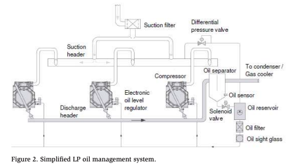
Systems that use low-pressure (LP) oil management also have an oil separator installed in the discharge of the TC compressors. The oil from the separator is fed into a separate reservoir at high pressure using an oil level sensor and oil transfer solenoid valve. The solenoid valve opens when oil is detected in the separator, and the oil is transferred to the reservoir. A simplified low-pressure oil management system is shown in Figure 2.
The pressure in the reservoir is reduced through a differential pressure valve installed in the vent line, which is connected from the reservoir to the compressor suction in single-stage systems. In two-stage systems, the vent line is connected to the intermediate pressure. The pressure in the reservoir is maintained with just enough pressure differential to move oil from the reservoir to the compressor crankcase through the electronic oil level controllers. Any gasket used in the spring-loaded mechanical pressure regulating valve installed in the oil vent line needs to be compatible with CO2.
This oil management system enables lower oil temperature and pressure for the compressors. As a result, the system will have better efficiency due to less superheat imposed on the refrigerant vapor. Reduced oil foaming in the compressor crankcase is also expected because less refrigerant is dissolved in the oil.
Oil Management for Two-Stage Systems (“Conventional” Supermarket Booster)
TC CO2 systems have been used by supermarkets worldwide since 2004. The concept has developed to meet the demand for future-proofing installations against growing refrigerant regulations. Key benefits include the use of a non-flammable refrigerant, excellent temperature control across a wide variety of temperatures, and good energy efficiency especially in cooler climates.
Usually, the compressor racks are designed in a booster system configuration for medium and low temperature applications. The most common TC CO2 booster system is designed with the flash gas bypass (FGB) principle. The gas from the LT compressor is mixed with gas from the flash gas bypass as well as the MT evaporators.
TC CO2 booster systems are typically equipped with an active oil management system. Based on the combination of high CO2 vapor densities and highly miscible oil, the return of lubricant from the DX evaporators is not challenging. A simplified low-pressure oil management system for TC CO2 booster systems is shown in Figure 3.
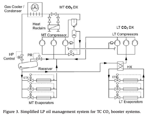
Due to the widespread and growing use of this system architecture, we will spend time discussing aspects of the system’s oil management as a baseline before moving on to more industrial applications.
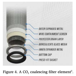
Coalescing Oil Separators
For TC CO2 operations, oil separators with coalescing filter cartridges are required as they provide better performance compared to conventional types (e.g., impingement screen, centrifugal). Rather than using impingement screens, most coalescing oil separators employ borosilicate matrix filters which cause tiny oil droplets to collide and, as a result, become large enough to force onto the outer drain layer of the filter. Droplets are collected at the bottom of the separator. An example of a CO2 coalescing filter element is shown in Figure 4.
Oil Separator Control
An oil level sensor located near the bottom of the coalescing oil separator controls the operation of a high-pressure solenoid valve installed in the oil return line between the oil separator and the oil reservoir. When a certain oil level is reached in the separator, the solenoid valve opens and forces oil to travel to the reservoir which is at a lower pressure.
Oil Reservoir Pressure
A lower reservoir pressure induces oil movement from the separator. Oil reservoir pressure is reduced by a vent line connected to the suction header of a compressor suction group. With TC CO2 booster systems using flash gas bypass technology, the vent line should be connected to the suction pressure level of MT compressors. It ensures oil flow from the reservoir to the level controllers for all compressors. There is an oil differential pressure valve installed in this vent line to keep the oil reservoir pressure above the suction pressure of the compressors. The required pressure difference depends on the boundary conditions, with pressure differences between 35 and 65 psid normally necessary to ensure a constant oil flow rate to the oil level controllers.
Oil Charge/Volume
For most supermarket TC CO2 boosters, the volume of the oil reservoir should be twice as large as the entire oil volume of the compressors. This seems to be adequate for balancing out temporary higher oil carry-over rates while providing additional storage capacity and preventing compressor oil starvations during transient conditions.
If the oil reservoir is too small, there will be a potential risk of it very quickly emptying during part load operation. As a result, the compressors may have a lack of oil and risk hot gas bypass via the oil circuit. At full load operation, a small oil reservoir could be overfilled and risk exceeding the oil level controller’s maximum operating pressure differential, and as a result compressor flooding can occur.
An oil level sensor should be installed inside the oil reservoir to ensure that the compressor’s oil level controllers will only open if the oil level in the reservoir is sufficiently high. This is to avoid a hot gas bypass to the compressor crankcases.
Oil Management Adjustments
Nozzle cross-sections of the oil level controllers: The oil level controller nozzles used for limiting the oil flow rate are adjusted as a function of the pressure difference according to the manufacturer’s specifications. This is extremely important because a large amount of refrigerant is dissolved in the oil due to the high upstream pressure. If pressure is subsequently reduced to the level of the crankcase pressure, the refrigerant rapidly becomes gaseous and turns the oil into foam.
Filling time of the oil level controllers: If the continuous filling time rate is too high, considerable foaming will occur, resulting in liquid slugging, increased oil carry-over rate (OCR), insufficient oil level control, and lack of oil. Ideally, there are adequate filling intervals with oil level measurement intervals in between (e.g., 1 s filling and 9 s measuring). The intervals can be adjusted for a given system.
Pressure in the oil reservoir: It is recommended to maintain a lower pressure oil management system. A good target is 35 to 65 psid and a maximum of 85 psid between the oil reservoir and the highest suction pressure in the system. The vent line is therefore routed into the corresponding suction gas line.
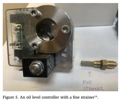
Oil Filters/Solenoid Valve Maintenance: The use of an oil filter installed after the oil reservoir is important to keep the oil clean and protect the oil level controllers and solenoid valves. Some oil level controllers come with a fine strainer integrated into the oil connection to prevent the solenoid valve seat from getting dirty, while others do not have an internal filter. In such cases, an external oil filter is required to protect the solenoid valve. An example of an oil level controller with a fine strainer is shown in Figure 5.
Oil Return Pipe Sizing
Excessive pressure drop in the oil return lines must be avoided as otherwise degassing effects due to pressure reduction can adversely affect the oil supply to the compressors. In some cases where the oil return line diameters and solenoid valve orifices are too small, there will be a potential risk of operating the oil separators overfilled and oil reservoirs emptied because of the insufficient oil flow imposed by the small oil return lines. System designers must keep in mind that as they scale up refrigerant pipe sizes, they must also consider scaling up ancillary pipelines such as the oil management header.
Oil Separator Sizing
Oil separators also need to be properly sized by taking into consideration not only the pre-defined design conditions but also the transient conditions (e.g., during pull down, defrosting terminations, re-starting the system after a power outage). These conditions require the compressor to operate outside the design conditions with higher suction pressure. With higher suction pressure, the compressor mass flow is increased and, as a result, oil separator capacity may be undersized with reduced separation performance.
Another factor in oil separator sizing and performance is the ambient and condenser performance. As the condensing temperature drops, so does the pressure inside the separator. As a result, the specific volume of the refrigerant is increased which increases the velocity through the separator, potentially reducing its performance.
A recommended approach to evaluate these conditions would consist of verifying the compressor mass flows in both design conditions and worst-case scenarios. A common worst-case scenario is when the system operates at the highest evaporating temperature and lowest condensing temperature or gas cooler outlet temperature.
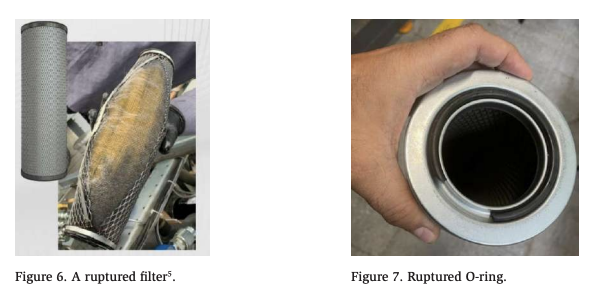
If the oil separator’s maximum allowable pressure drop is exceeded, the coalescing filter and O-rings can be damaged. In addition, coalescing filters eventually become contaminated and need to be replaced. Waiting too long to replace a contaminated filter can result in a ruptured filter and O-rings as shown in Figures 6 and 7. If oil is missing in the oil reservoir, it should be checked that the differential pressure across the separator is lower than the manufacturer’s recommendations (e.g., < 15 psid).
Finally, heating the oil separators/reservoirs is recommended to provide additional protection against condensation and flooding during standstill periods.
Combining Oil Separators in ParallelI
If the capacity of an oil separator is exceeded for a given application in large systems, the use of oil separators in parallel may be necessary. For parallel oil separator applications, it is recommended to have the inlet of the separators evenly distributed to prevent losing separation efficiency. When two oil separators are connected in parallel, the discharge flow must be split using a wye tee to utilize the oil separators equally. Otherwise, one of the oil separators may get a higher mass flow rate than the other, leading to unequal distribution of oil.
Oil Management for Two-Stage System with Parallel Compression
The next level of complexity in TC CO2 booster systems is parallel compression. Not to be confused with having “multiple compressors in parallel,” parallel compression is a term used to describe a dedicated suction group to compress the flash gas of the main liquid receiver. The compressor group operates at an interstage pressure higher than the medium temp compressor group. This compressor group is often referred to as “HT” for high temp. Due to this reduced pressure ratio, the flash gas is compressed at higher volumetric and isentropic efficiencies, leading to overall improvement in the coefficient of performance (COP).
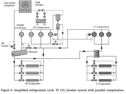
The active oil control used with CO2 parallel compression booster systems is very similar to the TC CO2 booster systems with FGB. The discharge lines from both MT and HT compressors are connected to the same discharge header. The discharge gas from these two compressor stages passes through the same oil separator, where the oil is separated and sent to an external oil reservoir as shown in Figure 8.
As mentioned previously, the pressure in the reservoir is controlled at a lower pressure (35 to 65 psid) through an oil differential pressure valve connected from the reservoir to the highest suction pressure in the system to allow oil to move from the reservoir to all of the connected compressor oil sumps.
Scaling up Traditional CO2 Transcritical Boosters for Industrial Use
Industrial is a somewhat subjective term that can relate to size, technology, or application. As CO2 systems become more common in the commercial world, many original equipment manufacturers (OEMs) are finding that there are opportunities for these systems in industrial environments. The systems can be very similar to larger, scaled-up versions running today.
Already, booster systems have become more popular for large systems with LT, MT, and HT applications combined to optimize system efficiency. Today, large cold storage facilities and food processing plants in North America designed for LT, MT, and HT applications can exceed 1400 TR of cooling capacity. Some of these systems are using more than 50 compressors distributed in multiple modular racks in TC CO2 booster configurations with parallel compression.
The use of the TC CO2 booster in an industrial environment can lead to certain challenges. For example, the evaporating temperatures may be lower, leading to higher compression ratios and greater part load challenges. Furthermore, in general, industrial applications such as cold storage facilities usually have a much larger LT load than MT load. This is the reverse of the commercial world situation where a typical supermarket may have < 40% of its load at LT conditions.
Another challenge when moving into the industrial space is the length of piping. As mentioned previously, oil management systems with DX evaporators rely on miscible oil to return to the suction of the (LT) compressors. Extensively branched piping commonly found in industrial applications should be designed to return the oil with enough gas velocities at full and part load operations without causing excessive pressure drops in the piping.
To ensure that the oil management system performs as expected, the system designer should also properly size all components such as the oil separator, oil reservoir, oil return line diameters, solenoid valve orifice, oil level sensors, and oil level controllers, as well as recover the oil that finds its way through the system.
For large systems, the volume of the oil reservoir could be generously sized (even up to 10 times bigger than the total oil of the compressors). The amount of oil circulating in a system varies depending on the system operating conditions, system cooling capacity, size of the piping, and distance from the evaporator to the parallel compressor racks. The volume of the reservoir must be sufficiently large to compensate for different oil circulation rates in the system (e.g., increased oil return from evaporators after defrosting, pull down, etc.).
Commercial DX vs. Industrial Oil Collection
As already discussed, commercially sized systems with DX evaporators lend themselves to simpler oil management systems because the oil that carries past the separator will travel directly back to the suction of the compressor.
With many traditional industrial systems, it is common to have flooded evaporators, liquid recirculation, and/or large suction accumulators where oil is often collected. With ammonia, this oil is conveniently heavier and can be easily collected in an oil pot for disposal. However, with CO2, the density of the refrigerant is greater than the oil, negating an oil pot as a solution. Consequently, the oil type for a CO2 system is typically chosen to be miscible to allow even distribution (and extraction) of the oil in the liquid refrigerant.
To return oil, an oil recovery system will be required, utilizing an oil rectifier to distill oil from the refrigerant.
Oil Rectifier by Internal Heat Exchanger
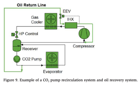
Oil rectifiers can be designed and employed in a variety of system configurations. Figure 9 introduces the concept in a simple single-stage system utilizing a liquid CO2 pump. Note that the oil separator, which may be used in addition to an oil rectifier, is not shown.
A liquid and vapor mix of refrigerant is pumped into one side of the internal heat exchanger (IHX). A higher-temperature refrigerant (from, for example, the compressor discharge line) feeds the other side of the heat exchanger. As a result, oil and refrigerant are separated by evaporating the refrigerant to avoid wet operation (at the compressor), leaving only the oil. Oil is then carried up to the main suction line by the gas velocity in the heat exchanger.
The use of an electronic expansion valve (EEV) is recommended to meter the liquid/ oil mixture with a minimum superheat (e.g., 18°F). This superheat is necessary because it is assumed that droplets of refrigerant will remain entrained with the oil. Monitoring the compressor discharge temperature is also recommended, as suction superheat can vary quickly due to transient liquid.
Oil Carry-Over Rate
The amount of oil moving past a component as a fraction of the total mass flow is referred to as the oil carry-over rate (OCR).
As discussed earlier (see Oil Separators), there are many factors that will affect the performance and OCR leaving the separator, such as the OCR of the compressor.
There are several factors affecting the OCR for a given compressor. Refrigerant mass flow has the greatest influence on OCR and can change based on compressor frequency, suction superheat, suction pressure, etc. In addition, oil foaming, temperature, and the oil level within the crankcase will also affect the OCR.
Amount of Oil to Recover
The amount of oil that is rectified must match the amount of oil carrying past the oil separator. To accomplish this balance, there are three factors that must all be in harmony: the compressor and oil separator performance, the concentration of oil in the system, and the % of mass flow being rectified.
If we assume a typical oil carry-over rate of 100 ppm (99.99% effective), then we would assume that 0.01% of the discharge stream leaving the separator is oil.
Obviously, having a lot more oil in the system is not desirable, but to make the oil rectification efficient and reliable it is assumed that we would need roughly 1% of the total system charge to be oil.
The last factor to consider is the mass flow of this mixture entering the IHX via the EEV. To arrive at 0.01% oil, 1% of the total refrigerant mass flow must be pumped through the IHX to create the proper balance of oil supply and demand.
To summarize:
Percentage oil in system (1%) x Percentage of Total mass flow (1%) = Amount of oil leaving separator (0.01%).
If oil separation efficiency decreases (resulting in higher OCR), then either the percentage of oil existing in the rest of the system (receivers, pumps, evaporators) or the percentage of the total mass flow rate must be increased in order to maintain balance.
Flooded Evap Oil Rectification with Venturi
In a typical flooded system, a pump provides the necessary mass flow to move the refrigerant, as a pressure difference does not exist. It is possible in some scenarios to have a refrigerant move via the venturi effect to return the oil to the compressor. This type of oil recovery system is typically utilized with gravity-flooded evaporators. As the oil accumulates in the liquid separator, oil rectifiers are required for recovery.
The rectifier is a small IHX that evaporates some of the refrigerant liquid from the separator and returns it to the compressor suction line, as shown in Figure 10.
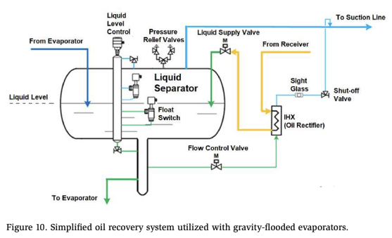
As the refrigerant and oil enter the IHX, the refrigerant boils off due to the liquid line temperature providing a heat source. At this point, the vapor refrigerant moves through the IHX as the suction line causes a pressure difference between the inlet and outlet of the IHX. As the refrigerant travels through the IHX, this causes a venturi effect to take place across the IHX, drawing in a liquid refrigerant/oil mixture from the liquid separator. The vapor refrigerant carries the oil back to the compressor suction line at a controlled rate. To ensure proper operation, the IHX must be installed below the operating liquid level inside the separator. The flow control valve installed in the inlet of the IHX is adjusted in such a way that there are no drops of liquid refrigerant seen in the sight glass to ensure superheat of the oil/refrigerant mixture.
Example of a Single-Stage Flooded/Liquid Recirculation Application: Ice Rinks
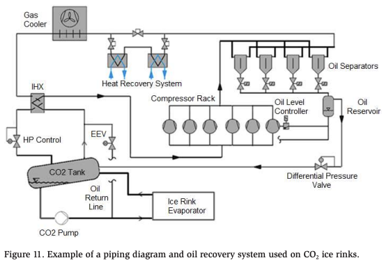
Recent years have seen the development of CO2 flooded systems used in the design of ice rinks. Instead of chilling a brine (e.g., calcium chloride, glycol), liquid CO2 flows directly under the rink slab, which acts as the primary evaporator, directly cooling the floor. As a result, the compressors operate at a higher suction pressure, thus achieving an increased coefficient of performance (COP) compared to chilling a secondary coolant. Uniform ice temperature coupled with direct heat transfer between the CO2 and the rink slab helps to maintain the quality of ice requirement.
A Unique Coil
The evaporator “coil” is specially designed and built in place to operate with the CO2 recirculation pump at pressures corresponding to the evaporating temperature (e.g., 400 psi). Oil and liquid CO2 mixture are taken after the CO2 pump to recover oil in an oil rectifier (see the section Oil rectifier with IHX).
Oil Management
The amount of oil circulating through the system varies depending on the operating conditions and the number of ice sheets. For this reason, the volume of the oil reservoirs is generously sized. As mentioned previously, it should provide additional storage capacity 5 to 10 times as large as the total oil volume of the compressors.
Greater compressor capacity is required during ice-making operations (or during any high heat loads). Thus, a higher OCR is expected to occur due to the higher evaporating temperatures. The oil leaves the compressors and travels throughout the system but does not return to the compressors at the same rate as it left. Consequently, oil reservoirs with large volumes are required to offset the deficit of oil balance that is not returning from the evaporator and CO2 recirculation tank to the compressors.
Once the ice sheet set point temperature is reached, the capacity and OCR are reduced. Thus, the oil rectifier is able to catch up and return more oil back to the compressors and oil reservoir. Figure 11 shows an example of a piping diagram and oil recovery system (including oil separator, oil reservoir, and oil-fed line).
The success of these systems has led to repeat configurations. The unique aspect of directly absorbing heat into CO2 that is compressed creates greater control and, therefore, quality of the ice.
Example of Two-Stage Industrial TC CO2 with Individual Separators
Up to this point, we have only discussed the separation of oil after the MT compressors in a booster configuration. This is because the LT compressors are directly feeding the MT compressors their oil carry-over and simplifying the oil management. However, as systems grow in size and complexity, it may make sense to add oil separation to the LT stage.
As shown regarding the topic of oil rectifiers, oil separation plays a principal role in the amount of rectification required. A lower amount of oil that leaves the compressor room means that the overall concentration can be reduced and/or the % of refrigerant that needs to be sent through the rectifier. By adding dedicated separators to the low temp stage, the overall separation is improved. However, now there is added complexity as oil migration may create oil issues for a compressor group.
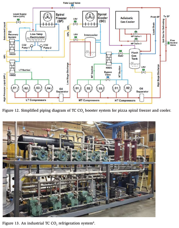
An example of this TC CO2 system was recently installed at Amy’s Kitchen 65,000-square-foot pizza production facility in San Jose, California, as shown in Figures 12 and 13. The refrigeration system was designed with an architecture based on a TC CO2 booster with parallel compression and an adiabatic gas cooler to meet the customer’s energy efficiency, environmental sustainability, safety, and compliance requirements. Thus, the compressor rack layout is still as compact and lean as a conventional booster system dedicated exclusively to refrigeration.
System Description
- 80 TR of capacity to a spiral freezer operating with flooded evaporators at -40°F saturated suction temperature (SST).
- 100 TR of capacity to a spiral cooler operating with DX evaporators at 30°F SST.
- The compressor rack is equipped with nine semi-hermetic reciprocating compressors:
- Low Temp: Qty 4
- Medium Temp: Qty 3
- Parallel / High Temp: Qty 2
- There are three primary vessels for handling the liquid refrigerant:
- Flash Gas Tank: Operates at 40°F via the HT compressors
- Intercooler: Operates at 30°F via the MT compressors
- Low Temp recirculator: Operates at -40°F via the LT compressors
- Other key components:
- Adiabatic gas cooler
- Hot gas defrost is used for LT evaporators and off-cycle defrost for MT evaporators.
The oil management system consists of three oil separators, one for MT and HT compressors, and two for LT compressors. The oil collected from the oil separators is sent to the oil reservoirs, and then to the compressors (which have oil level controllers) when required. The oil reservoirs are vented to provide appropriate pressure differences to move the oil to the compressors.
The Intercooler Vessel and Oil Management
The intercooler vessel is an interesting addition to this system and one of the hallmarks that makes it uniquely “industrial” in comparison to a typical CO2 booster system.
The vessel performs several functions. One is to accept the discharge stream of the LT compressors so that the system has control of the suction temperature of the MT compressors. This enables the compressors to operate within accepted parameters and without reliance on certain load ratios between the MT and LT compressors. However, this vessel prevents oil that leaves the LT compressor separators from entering the MT compressors directly.
The vessel also provides an accumulator function for the MT spiral cooler. Any liquid droplets that pass through these evaporators can be separated and provide protection to the compressors. However, again, oil that is in this part of the system remains in the intercooler.
To solve this issue, oil recovered from the intercooler is sent to the low temperature recirculator where it homogenizes with the existing liquid refrigerant/oil mixture. A small portion (around 1%) of the pumped liquid recirculation is sent through a heat exchanger (oil recovery system) to boil off the refrigerant so that the remaining oil can enter the suction line of the LT compressors. Because this suction line is already passing through an IHX, additional compressor protection from liquid droplets is provided.
With this system configuration, there is one big challenge: most oil is likely to collect in the oil reservoir of the LT compressors. This means there is no pressure difference to move the oil to the MT or HT compressors. To solve this, the LT oil reservoir is able to be pressurized by the MT discharge (in addition to being able to bleed down to pressure more appropriate for feeding the LT compressor). As a result, the oil reservoirs are able to feed any compressor as needed.
In the end, this system has proven to be a great solution for Amy’s Kitchen pizzas. With all stainless-steel piping, parallel CO2 compression, and a well-thought-out dedicated LT/MT oil management system, this is truly a one-of-a-kind industrial transcritical solution.
Oil Type
It is vital to ensure that the compressor is properly lubricated to operate correctly over its lifespan. Lubricants for CO2 systems must meet specific requirements, and several studies have been conducted over the past two decades to identify the best lubricants for CO2 compressors and systems. This research has led to the widespread use of polyolester (POE) oils which are highly soluble and miscible. There are other types of oil, such as poly alkylene glycol (PAG) which is recommended for highly demanding CO2 applications such as heat pumps, where pressure and temperature levels are typically significantly higher than usual.
Specially formulated POEs can be used in large and branched pipe networks (e.g., supermarkets, industrial applications). However, due to their negative effects on viscosity and lubricity (tribology), these features require CO2 compressors with extremely robust and wear-resistant drive gears. Even more critical than the viscosity issue is degassing caused by system pressure fluctuations. As the pressure drops, any droplets of CO2 that are entrained in the oil will vaporize and threaten the boundary layer the oil is maintaining between surfaces.
Since POE oils have a high affinity for water, it is also a challenge to ensure the lubricant is stable. Oil dilution plays an important role in CO2 compressor design. As carbon dioxide is a strong detergent, it is essential to lubricate the compressor properly throughout its lifetime.
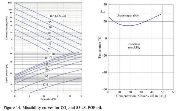
Miscibility curves of oils and refrigerants are an important consideration. Figure 14 illustrates an example Daniel chart and miscibility curve of CO2 with POE oil. Under pure conditions (100% oil, zero refrigerant), the lubricant has a viscosity of 85 cSt (centistokes). However, in real-life system operations, these ideal conditions cannot be replicated.
The amount of carbon dioxide diluted into the oil is always affected by the operating conditions of the system. For example, as pressure increases and/or temperature decreases, the oil is able to solve more refrigerant which reduces the viscosity. CO2 compressors must only operate with the type of oil approved by the compressor manufacturer. The different types of oils must not be mixed to prevent chemical reactions, and possibly poor lubrification properties.
Piping
As with any refrigeration system, proper sizing of piping is important not only for pressure drops but also for proper oil return when necessary. One of the advantages of CO2 is that it is more forgiving in terms of the relationship between pressure drop and saturated temperature penalty. For example, a 5 psid pressure drop with the compressor operating at a pressure equivalent to +20°F is less than 1 degree F penalty for CO2 (compared with nearly 4 degrees for ammonia).
Still, refrigerant lines should be sized to provide a minimum pressure drop at full load. In addition, if oil is returning from the evaporator to the compressor suction, it must also be sized to do this at minimum load conditions.
Velocities for CO2
Suction Lines: This high operating pressure/low-pressure drop situation allows evaporator and pipework designers a greater degree of safety. Additionally, the high density of the CO2 also aids oil return as the increased mass flow helps carry the oil through pipework, even at reduced loads. Generally, only 1000 to 1200 ft/min are required to carry oil along a CO2 suction line.
Liquid Lines (DX System): Liquid lines from the receiver to evaporators should be sized to maintain a velocity below 300 ft/min to minimize liquid hammer when solenoids or other electrically operated valves are used. The liquid condensate line from the condensers to receivers should be sized for a velocity of 100 ft/min or less to ensure positive gravity flow without incurring backup of liquid flow.
Liquid Lines (Liquid Recirculation Systems): A typical overfeed rate of 2:1 is recommended for CO2, whereas most liquid recirculation systems on other refrigerants use a higher overfeed rate (4:1 is common) to achieve good oil return and a constantly wetted coil. This overfeed rate will prevent oil logging in the evaporator even at low loads or with an iced-up evaporator.
Discharge Lines (After Separator): In general, CO2 discharge line velocities are about the same as other refrigerants, 1600 to 3000 ft/min. If the discharge gas velocity is too high, the oil separator efficiency is affected, and as a result the oil droplets are simply dragged upwards to the system rather than being separated.
Flash Gas Bypass Lines: 800 to 1200 ft/min
Defrost Lines: 1000 to 2000 ft/min
Suction Header Design
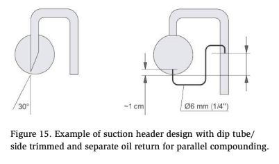
It is recommended that compressor suction lines be designed to enter the suction header on the topside. The suction lines from the header towards each individual compressor must be fitted into the suction header and the end tube cut at an angle of 30° or by a separate ¼” oil return tube as shown in Figure 15.
These configurations will result in a proper oil (or liquid refrigerant) return if either is accumulated in the suction header, to prevent the compressors from flooding. The suction header diameter should be calculated so that the gas velocity at full load operations does not exceed 800 ft/min. This is essential to create a laminar flow and favor equal distribution of oil and refrigerant to all compressors.
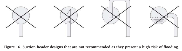
The suction header designs shown in Figure 16 are not recommended as they offer a high risk of flooding.
Discharge Header Design
It is recommended that the cross-section of the compressor discharge header (same diameter throughout) be as large as the total cross-section of the individual pipes. Alternately, a maximum flow velocity of 2000 ft/min should not be exceeded to prevent abnormal vibrations and noise. Due to the CO2 high pressure and the possibility of pulsation, larger systems will have stainless steel piping, while smaller ones will use copper-iron alloy piping with appropriate pressure rating. To prevent a drain-back of refrigerant and oil when flow rates are reduced or the compressor is turned off, individual discharge lines should be routed to lower elevations after leaving the compressor discharge valve.
The discharge header design should allow free gravity drainage towards the oil separator when the system is shut down. This prevents a potential risk to have the area of the discharge header obstructed with oil when system compressors restart.
Conclusion
This paper presents design considerations and recommendations to build a reliable and efficient oil management system for commercial as well as industrial transcritical CO2 applications.
First, we compared commercial oil management systems as a baseline for proven methods and discussed some of the unique challenges as the systems are scaled up to industrial-sized TC CO2 systems. We also studied recent industrial TC CO2 applications such as ice rinks and a food processing plant with respect to their oil management approaches.
Along the way, this paper explores different oil recovery approaches in flooded systems and DX systems, while also reviewing the selection criteria of the main oil management components such as oil separators, reservoirs, level controllers, piping, and lubricants.
With industrial transcritical CO2 systems becoming ever more popular globally, it will be important that the oil management employed in such systems be designed, installed, and operated properly to suit the demands and rigors of industrial settings.
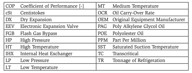
Nomenclature
References
- Javerschek, O., et al. 2021. Advanced Design for CO2 Compressors in Industrial Applications. 9th IIR Conference: Ammonia and CO2 Refrigeration Technologies, Ohrid. https://iifiir.org/en/events/9th-iir-conference-on-ammonia-and-co2- refrigeration-technologies
- Javerschek, O. 2008. Commercial Refrigeration Systems with CO2 as Refrigerant. 8th IIR Gustav Lorentzen Conference on Natural Working Fluids, Copenhagen. http://www.ammonia21.com/files/pdf_760.pdf
- Reichle, M. 2019. Mastering the Technology of Transcritical CO2 Applications. International Refrigeration Seminar, BITZER SCHAUFLER Academy, RottenburgErgenzingen, June 2019.
- Mannewitz, J., et al. 2018. Oil transport mechanisms’ inside semi-hermetic reciprocating compressors for CO2 applications, 24th International Compressor Engineering Conference at Purdue, 2018, https://docs.lib.purdue.edu/icec/2635/
- Gallaher, J. and Binette, P. 2021. Design and Troubleshooting of CO2 Transcritical Oil Management System, RETA National Conference, Schaumburg, IL.
- Rogstam, J., Abdi, A., Sawalha, S. 2014. Carbon Dioxide in Ice Rink Refrigeration. 11th IIR Gustav Lorentzen Conference on Natural Refrigerants. Hangzhou.
- Advansor, HillPhoenix. 2016. First U.S. Ice Rink to Use Sustainable CO2 Refrigeration. https://www.hillphoenix.com/wp-content/uploads/2017/08/ Case-Study-industrial-refrigeration-Mcdonald-ice-rink.pdf. https://www. hillphoenix.com/product/ice-rink-co2-system/
- Apcco Industrial Transcritical CO2 Refrigeration System. Amy’s Kitchen Pizza Production Facility, San Jose, California. 2021. https://apcco.net/projects/ transcritical-co2-refrigeration-system/
- BITZER KT-600-4 Technical Information. 2021. Parallel Compounding of BITZER Reciprocating Compressors. June 2021 Edition. https://www.bitzer.de/shared_ media/html/kt-600/en-GB/index.html?P=/html/kt-600/en-GB&N=index.html
- BITZER ST-600-2 Technical Information. 2006. Piping Arrangement for Screw Compressors. Sep 2006 Edition. https://www.bitzer.de/shared_ media/documentation/st-600-2.pdf?P=/doc/&N=st-600-2.pdf&utm_ source=BitzerSW&utm_campaign=pdf&utm_medium=Verweis
- Danfoss Application Handbook. 2020. Industrial Refrigeration Ammonia and CO2 Applications. 2020 Edition.
- ANSI/IIAR. 2018. Carbon Dioxide Handbook for Industrial and Commercial Refrigeration Applications. 2018 Edition.
- ASHRAE Refrigeration Handbook. 2018. Chapters 3 and 4, https://www.ashrae. org/
- AWA Oil Level Controllers, https://www.awa-armaturenwerk.de/fileadmin/pdfs/ tech_info/en/90000722_Rev00_en.pdf
- Temprite Coalescing Oil Separators, https://temprite.com/products/coalescentoil-separators/
- Henry Catalogue, http://www.henry-group.net/wp-content/uploads/2017/12/ Henry-Technologies_E1_Catalogue_Interactive_low.pdf
- Carrier Commercial Refrigeration Europe, https://www.carrier.com/commercialrefrigeration/en/eu/products/systems/powerco2ol/
- Linde Operating Instructions. 2003. Multi-Compressor Refrigeration Units. January 2003 Edition.
- BITZER KT-500-9 Technical Information. 2021. BITZER Refrigeration Compressor Oils for Reciprocating Compressors. June 2021 Edition. https://www.bitzer.de/ shared_media/html/kt-500/en-GB/index.html?P=/html/kt-500/en-GB&N =index.html
Acknowledgments
- Miguel Boscan, Application Engineering Manager, BITZER US, Inc.
- Manuel Reichle, Application Engineer, BITZER Kühlmaschinenbau GmbH
- Tim Henderson, Industrial Program Manager, HillPhoenix
- Gary Dunn, President, Apcco
- Steve Johnson, Senior Manager of Maintenance Operations, Amy’s Kitchen