2026 White Paper: Superheat Control in Transcritical CO2 Systems: Addressing the Challenges During Part-Load and Full-Load Operations
Author:
Giacomo Pisano, M.Sc. Engineering, DORIN USA
Abstract
CO2 has become a mainstream solution for numerous applications, including industrial and commercial refrigeration, heat pumps, and winter sport venues. Across all these applications, effective superheat control plays a key role in system efficiency and compressor reliability. Superheat varies significantly between part-load and full-load operations, as well as between summer and winter operations. In light of this, this work examines several transcritical CO2 system configurations and analyzes how improper superheat management could lead to severe performance and reliability issues, including efficiency decreases and compressor failure. It also describes potential system design enhancements aimed at mitigating the negative effects of improper superheat control to provide practical insights into the design of systems capable of maintaining high efficiency standards while preserving compressor reliability.
Introduction
Suction superheat control in transcritical CO2 refrigeration systems has a strong influence on system reliability (Pisano, 2025). In particular, accurate superheat control plays a key role in ensuring the longevity and efficient operation of compressors.
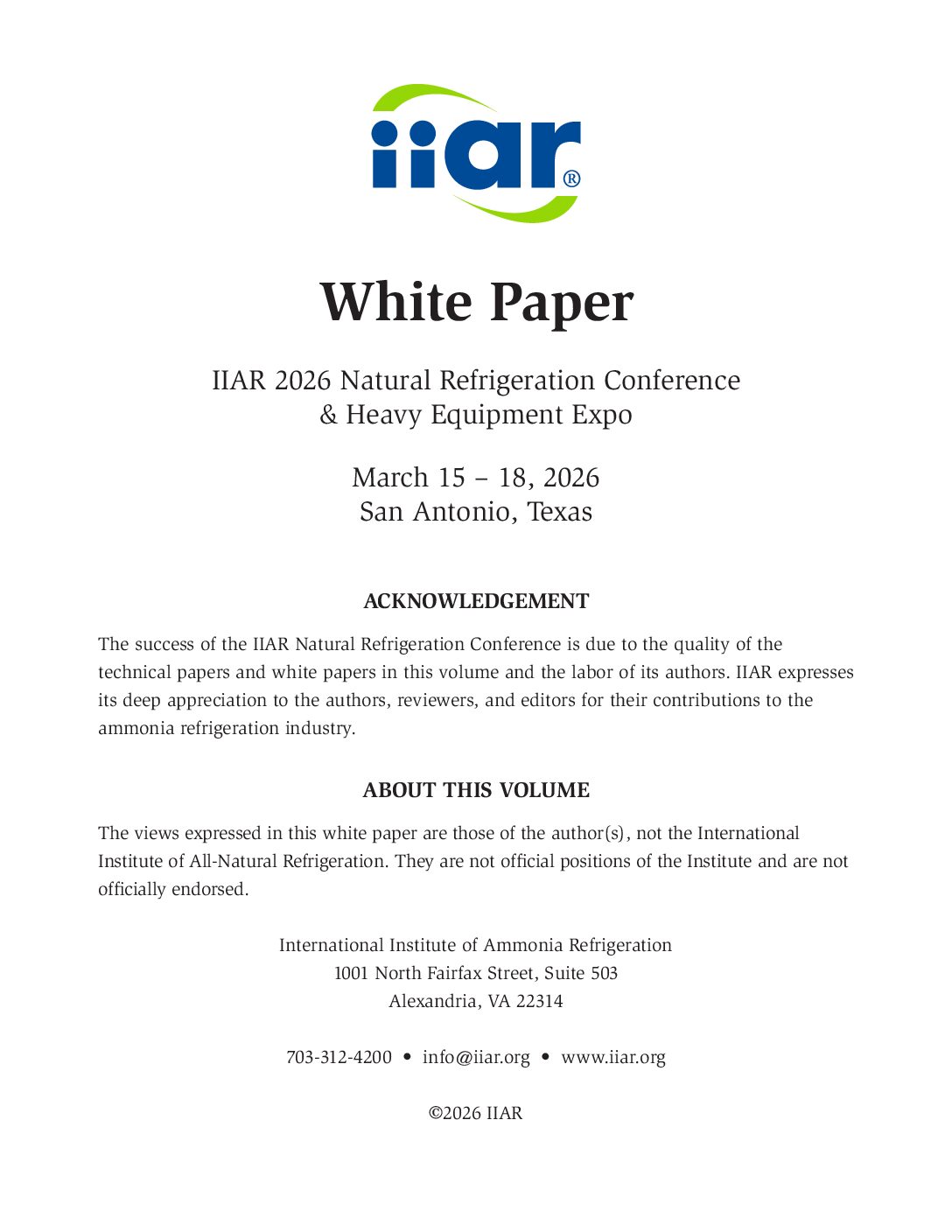
Suction superheat is defined as the difference between the compressor suction temperature and the refrigerant saturated temperature at a given boiling point; in other words, suction superheat represents the temperature increase of the refrigerant vapor above its saturation temperature after complete evaporation within the evaporator coil. Figure 1 illustrates this concept using a p-h diagram for a transcritical CO2 cycle.
Influence of Superheat on Compressor Reliability
Whenever liquid refrigerant does not fully evaporate within the evaporator coil, it may be drawn into the compressor suction line. From a reliability perspective, this occurrence is highly detrimental, as liquid refrigerant is a non-compressible fluid and will inevitably cause severe damage to the internal components of the compressor. Given that reciprocating compressors are the most widely adopted technology in transcritical CO2 applications (Pisano, 2022), typical failure mechanisms associated with this compressor type are discussed in the following sections.
Liquid Refrigerant Slug
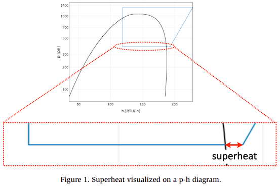
Liquid refrigerant slugging refers to occurrences in which a large volume of liquid refrigerant flows back into the compressor suction. Under such circumstances, compressors are at high risk of premature failure. In the case of reciprocating compressors, these failures often occur at the valve plate level, especially at the suction valve reeds. Specifically, during the compression stroke toward the upper dead point, the piston attempts to compress the non-compressible fluid, resulting in an extremely high mechanical load on the reed (Figure 2).
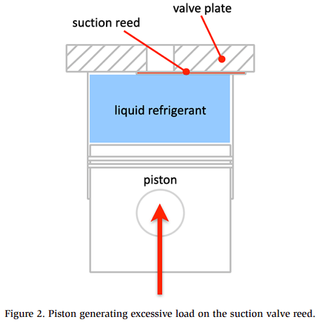
This results in damage to and the rapid failure of the suction reeds; the components often exhibit deformation consistent with heavy hammering. This failure mode is thus easily identified and referred to as liquid hammering. Figure 3 shows the typical appearance of a suction reed after exposure to a liquid slug.
It is therefore evident how liquid slugs pose a significant risk to compressor performance and system reliability, highlighting the importance of ensuring the complete evaporation of the liquid refrigerant before it reaches the compressor suction and of maintaining an appropriate level of superheat.
Insufficient Superheat/Wet Operation
This refers to cases where liquid refrigerant is almost completely boiled off within the evaporator coils, but the fluid stream entering the compressor suction still has a vapor quality in the range of 0.9–1. Under such circumstances, the residual liquid cannot be classified as a slug nor can it cause liquid hammering; indeed, this does not lead to rapid compressor failure in most cases.
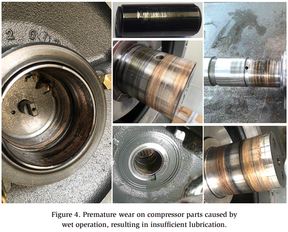
However, this phenomenon can lead to longer-term compressor-related issues. Under these conditions, the CO2 stream contains microscopic drops of liquid in the form of vapor spray, which can flash out the lubricant layer between the moving parts, resulting in a sudden decrease in the differential pressure generated by the oil pump. When this occurs, strong boundary friction develops throughout the compressor. In the case of reciprocating compressors, components such as shaft necks, bearings, piston skirts, cylinder walls, compression rings, and wrist pins can be subjected to severe lack of lubrication, which can ultimately result in premature wear (Figure 4).
Based on the failure modes described in the sections on liquid refrigerant slugs and wet operation, system designers and contractors should ensure that a sufficient level of suction superheat is maintained in order to avoid the return of liquid refrigerant to the compressor suction group. However, the opposite operating condition—i.e., excessive superheat—should also be considered; this occurrence is described in more detail in the following section.
Excessive Superheat
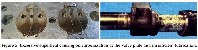
Excessively high superheat levels can adversely affect compressor reliability. Under such conditions, electric motors may overload and trip; these conditions can also result in excessively high discharge temperatures. This can result in highly detrimental consequences, such as oil carbonization, a lack of lubrication, and piston seizure on the cylinder walls. Figure 5 illustrates some examples of the damage that can be caused by excessive superheat.
In addition to reliability concerns, excessive superheat can negatively impact system efficiency. Specifically, an increase in the compressor suction gas temperature results in lower fluid densities, which in turn requires compressors with larger displacement volumes and higher motor power, resulting in increased energy consumption.
At present, there are more than 35,000 CO2 systems running worldwide (Shecco, 2024). Over time, there have been substantial improvements in the expertise of refrigerating contractors with regard to modern CO2 refrigeration applications. Consequently, failures caused by liquid refrigerant slugs have become increasingly rare in day-to-day operations. However, wet operation and compressor overheating remain relatively common due to the wide range of variables that influence the operating conditions of CO2 systems, as well as application-specific requirements and system design choices.
From the perspective of compressor reliability, the ideal superheat value ranges from 18R [10 K] and 54R [30 K] (Officine Mario Dorin S.p.A., n.d.-a). Strategies to mitigate wet operation and excessive superheat are discussed in the following sections.
Superheat: Challenges in CO2 Transcritical Systems
Figure 6 presents a representative layout of a CO2 booster system with parallel compression. This design is considered to be one of the most efficient architectures currently deployed in industrial refrigeration applications. The operating principles of this system have been analyzed in detail by Pisano (2024).
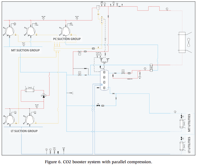
This layout includes a low temperature (LT) compression suction group, a medium temperature (MT) compression suction group, and a parallel compression (PC) suction group for removing the flash-gas within the intermediate pressure receiver. It is crucial to ensure that the compressors in each of these suction groups operate at an appropriate level of superheat; i.e., between 18R (10K) and 54R (30K). The following sections describe strategies for achieving proper superheat control for each suction group.
Low Temperature Suction Group
The LT suction group receives the CO2 vapor that returns from the LT evaporators. The suction saturation temperature for LT utilities often ranges between -30°F to -20°F (-34.4°C to -28.9°C); consequently, the suction piping between the utilities and the rack is typically subject to a consistent amount of thermal loss, which brings the superheat levels to a reasonable value.
However, operating conditions under which liquid CO2 does not fully evaporate must be considered, especially during peak loads. Under such conditions, LT compressors may operate with little or no superheat, leading to wet operation that may be highly detrimental to compressor reliability.
Conversely, lower load scenarios may result in excessively high return temperatures from the LT utilities; under these circumstances, particular care must be taken to prevent the LT compressors from operating at excessively high superheat levels, which can also negatively affect reliability as described in the Liquid Refrigerant Slug and Wet Operation sections.
Medium Temperature Suction Group
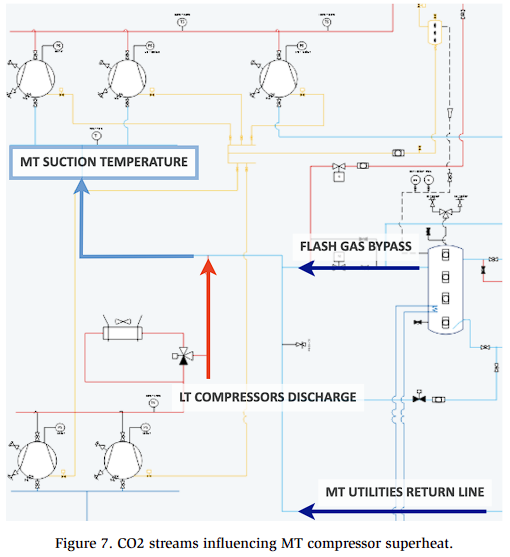
Suction superheat control in the MT suction group represents one of the most complex challenges in parameter control in a transcritical CO2 booster system. Figure 7 shows that the MT compressor suction superheat is the result of the interaction of several different refrigerant streams that vary in temperature and mass flow during full-load and part-load operations. These parameters also vary with ambient temperature, which changes throughout the year.
The primary refrigerant streams contributing to MT suction superheat include the following:
- Return line from MT utilities
- Flash gas bypass line
- Discharge line from LT compressors
These streams are discussed in more detail in the following sections.
Return Line from the MT Evaporators
Refrigerant returning from MT utilities is expected to be fully evaporated due to evaporator load requirements and thermal dissipation along the piping between the evaporators and the refrigeration rack. MT systems are typically designed to provide a total suction superheat in the range between 18–20°R relative to the saturated suction pressure of the MT compressors under full-load conditions.
However, during part-load operations, these superheat values may change significantly. As refrigeration load decreases, superheat values could increase well beyond the intended range, resulting in the compressor reliability issues described in previous sections.
Conversely, in overfed systems, such as pumped systems or ejector-based systems, the refrigerant is intentionally not fully evaporated within the evaporator coils (Pisano, 2025). These operating conditions could potentially lead to wet operation in the compressors.
Flash Gas Bypass Line
Flash gas accumulates above the liquid level within the intermediate pressure receiver (IPR). Since flash gas has a negligible contribution to heat transfer, it is typically throttled toward the MT suction group rather than being circulated through the evaporator coils (Pisano, 2024). Inside the IPR, the flash gas is a saturated liquid with a quality equal to 1. However, once throttled toward the MT suction group, the fluid stream is no longer comprised solely of vapor and may contain a liquid fraction (Figure 8).
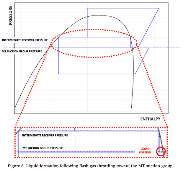
The presence of a partially evaporated fluid stream being throttled toward the MT compressor suction group is not ideal, as this may lead to wet operation. This risk becomes more pronounced with increasing heat sink temperatures: indeed, in aircooled systems, an increase in ambient temperatures leads to an increase in the amount of flash gas (Figure 9).

Figure 9 presents a p–h diagram depicting the amount of flash gas present within the IPR at gas cooler outlet temperatures of 90°F (32.2°C) and 110°F (43.3°C), depicted with blue and purple lines, respectively. It is clear that the higher gas cooler outlet temperatures result in a substantially larger flash gas fraction being bypassed to the MT suction group. As a result, air-cooled systems operating under high ambient temperatures are more susceptible to wet operation at the MT compressors, putting these components at higher risk of damage.
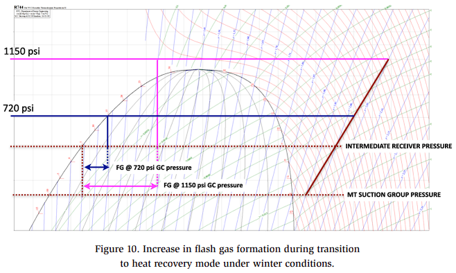
In addition to high ambient temperature conditions, winter operation and heat recovery pose unique challenges. Under cold ambient conditions, air-cooled systems often operate in subcritical mode, resulting in a very small amount of flash gas in the IPR as CO2 condenses in the high-pressure heat exchanger. However, if heat recovery is integrated within the system design, such as for the production of sanitary hot water or comfort heating, the system head pressure must be increased to raise the enthalpy of the high-pressure stream, allowing it to reach the desired compressor discharge temperature. When this transition happens—for example, when a system operating in subcritical mode under winter conditions is used to produce hot water and raises its discharge pressure—the amount of flash gas in the IPR can increase rapidly, potentially leading to wet operation at the MT compressors. This phenomenon is illustrated in Figure 10.
LT Compressor Discharge Line
The discharge line from the LT compressors also plays a significant role in determining the MT compressor suction superheat. Despite the relatively small pressure ratio, LT compressor discharge temperatures typically reach 140°F (60°C) due to the presence of an LT internal suction heat exchanger. Since this discharge flow is directly streamed toward the MT compressor suction, high-temperature gas from the LT compressors can potentially result in excessive superheat at the MT compressors, potentially leading to compressor damage.
Parallel Compression Suction Group
Suction superheat control in the PC suction group is crucial for the reliability of the parallel compressors as well as effective oil management. Parallel compression is one of the most widely adopted architectures for improving the efficiency of transcritical CO2 systems (Pisano, 2024). Flash gas generated within the IPR is no longer throttled toward the MT suction group but is instead compressed directly to the gas cooler pressure by the PC suction group. Consequently, parallel compressors draw the flash gas directly from the IPR, typically with little to no superheat. This can have a detrimental effect on compressor reliability by promoting oil degassing due to suction pressure fluctuations, as well as increasing oil entrainment throughout the system (Pisano, 2025).
Superheat Control and Risk Mitigation Strategies
The previous sections described the significant variability in superheat for the LT, MT, and PC suction groups, which is primarily dependent on the LT/MT load ratio and ambient temperature conditions. Accordingly, the following scenarios may occur:
- Both LT and MT systems running at full load, under either high or low ambient temperatures, with or without parallel compression.
- LT operating at part load while MT operates at full load, under either high or low ambient temperatures, with or without parallel compression.
- LT operating at full load while MT operates at part load, under either high or low ambient temperatures, with or without parallel compression.
- Heat recovery operation under low ambient temperatures.
Compressor Staging
The first approach to mitigating risks associated with poor superheat management is the implementation of an accurate compressor staging strategy for each suction group. Compressor staging depends on the part load strategy, which is highly application-dependent. For example, cold storage facilities, blast freezers, and iceskating areas have significantly different part-load strategies.
Nevertheless, appropriate compressor staging used in conjunction with an accurate compressor frequency drive can substantially improve superheat control. It is therefore crucial to design each suction group with an appropriate number of compressors such that the smallest inverter-driven compressor provides the minimum refrigeration demand required by the system during low temperature operation (e.g., during cold ambient conditions with minimum condensing or gas cooler outlet temperatures).
When the smallest compressor in each suction group is inverter-driven and has been selected to be one or two sizes smaller than the other compressors in its group, fine capacity modulation can be achieved, allowing for sufficient superheat management. Consequently, a variable speed drive that is large enough to absorb the capacity variables associated with starting or stopping a fixed-speed compressor can be distinct advantage.
In addition to proper compressor staging, the following sections describe additional strategies to address superheat variability and mitigate its associated risks, with the aim of maintaining suction superheat within the recommended range of 18–54°R (10–30K) for each suction group.
LT Suction Group
A suction superheater is often used to mitigate risks associated with insufficient superheat. This device is a heat exchanger that heats the return line from LT utilities using liquid refrigerant as the heat source. As a result, the LT return gas is superheated while the liquid refrigerant is subcooled.
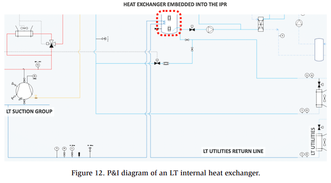
One modern design incorporates the use of an IPR, which not only holds the main refrigerant charge but also contains an embedded heat exchanger coil that is connected to the LT return line. Figure 11 illustrates the interior of this heat exchanger, while Figure 12 presents the internal design of the heat exchanger in a P&I diagram.

From an energy efficiency perspective, the two effects introduced by this arrangement tend to balance each other: increased suction superheat reduces gas density—which negatively affects both compressor motor cooling and refrigerant mass flow rate—but liquid subcooling positively influences the performance of the system. These observations are supported by performance calculations conducted using a compressor manufacturer’s selection software (Officine Mario Dorin S.p.A., n.d.-b; Figure 13).
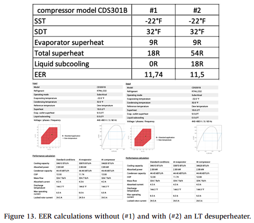
Figure 13 shows the same compressor operated at identical SST, SDT, and evaporator superheat, without (#1) and with (#2) an internal heat exchanger. Despite the compressor with an internal heat exchanger providing a larger amount of total superheat by subcooling the liquid exiting the IPR, both setups have very similar energy efficiency ratios (EER).
MT suction group
Of all the components, superheat control in the MT suction group is the most complex. The MT compressor suction temperature is influenced by multiple refrigerant streams, each subject to significant variations in mass flow rate and temperature. These interactions can lead to two primary operating risks: compressor wet operation and compressor overheating.
Strategies to Mitigate Compressor Overheating
Preventing compressor overheating requires maintaining compressor operation within the manufacturer’s allowable operating envelope while keeping superheat below the maximum recommended value.
In certain industrial refrigeration applications, such as freezing tunnels or large cold storage facilities, the LT load may significantly exceed the MT load. In such cases, the return mass flow from the LT compressors is relatively large, which cannot always be mitigated by return gas from the MT utilities or flash gas flow, especially during operation in colder ambient temperatures when flash gas generation is minimal.
Under such circumstances, the MT suction group superheat may increase significantly, resulting in compressor overheating; it is thus crucial to incorporate measures that mitigate this risk. Some examples of such mitigation strategies are as follows:
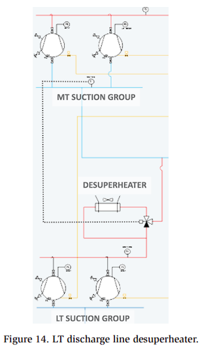
- LT discharge line desuperheater. The LT discharge line desuperheater consists of a heat exchanger installed in the LT compressor discharge line. This device is typically being engaged when the MT suction group is exposed to excessive superheat (>54°R [30K]). Under such conditions, a three-way control valve directs the refrigerant flow through the heat exchangers, thereby cooling the gas stream before it reaches the MT compressor suction (Figure 14).
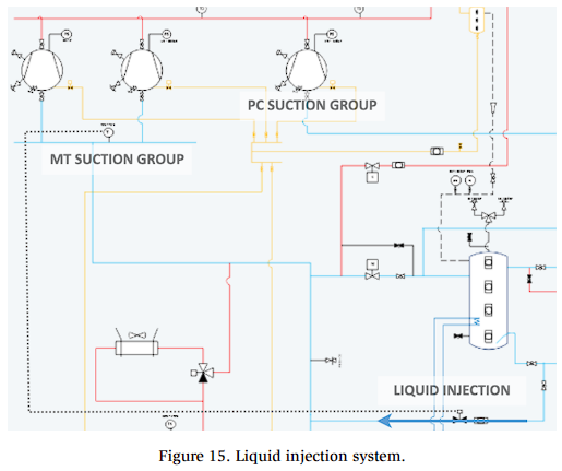
- Liquid injection. An alternative approach to reducing excessive MT suction group superheat is the implementation of a liquid injection line. This line brings liquid refrigerant directly from the IPR, bypassing both MT and LT utilities. It is controlled by a solenoid valve that activates when the superheat exceeds the 54°R (30K) threshold. The principle of operation of liquid injection is shown in Figure 15.
Preventing compressor wet operation requires different mitigation strategies depending on the system architecture. Overfed and dry expansion systems are discussed separately in the following sections.
Overfed Systems: Strategies to Mitigate Compressor Wet Operation
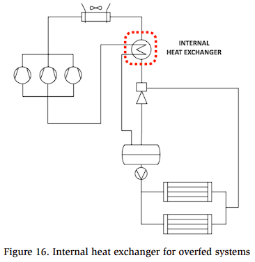
- Internal heat exchanger. An internal heat exchanger is employed in overfed configurations, such as pumped systems or ejector-based systems. This component is typically a plate heat exchanger that heats gas returning from the low-pressure receiver using the gas cooler outlet stream as the heat source (Figure 16).
- Vessel design. Proper vessel design is essential to ensure effective liquid–vapor separation, allowing only small liquid droplets to enter the suction line.
Dry Expansion Systems: Strategies to Mitigate Compressor Wet Operation
In the case of dry expansion systems, MT compressor wet operation can be mitigated using the two primary approaches.
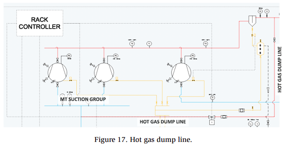
- Hot gas dump. This system diverts a portion of the MT compressor discharge flow back to the MT suction group. The system is typically activated when the rack controller detects suction superheat below 18°R (10K); at this point, a solenoid valve is opened that feeds hot gas through the dump line, increasing MT compressor superheat to the desired level. Figure 17 illustrates the hot gas dump configuration in a P&I diagram.
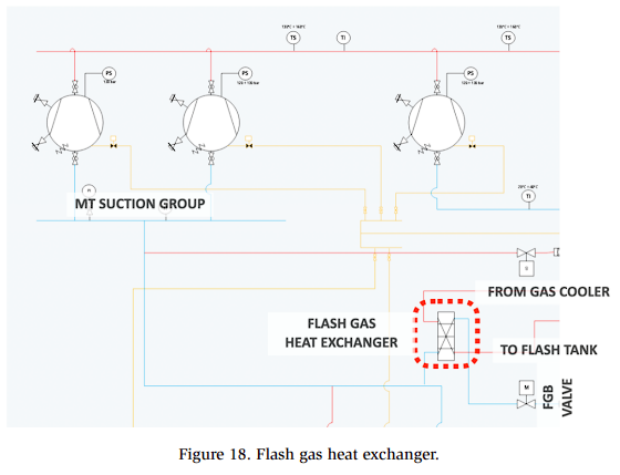
- Flash gas heat exchanger. As discussed in the section on the flash gas bypass line, flash gas from the IPR is throttled toward the MT suction group, which is a fluid stream that may not be fully evaporated. The risk of MT compressor wet operation is further increased during LT part-load conditions, when the warm gas stream from the LT system may be minimal or absent. Under these conditions, especially when operating under warm ambient temperatures, a large amount of flash gas may be generated (see Flash Gas Bypass Line), resulting in insufficient superheat or even wet operation. To mitigate this risk, a heat exchanger can be installed to heat the flash gas and boil its liquid fraction using the gas cooler outlet stream as the heat source. Figure 18 presents this flash gas heat exchanger configuration in a P&I diagram.
PC Suction Group
Superheat control in the PC suction group is critical to ensuring compressor reliability and preventing excessive oil carryover (Pisano, 2022). In the absence of appropriate mitigation measures, PCs can draw saturated gas from the top of the IPR, leading to insufficient superheat or even wet operation if liquid management strategies are not employed at the receiver.
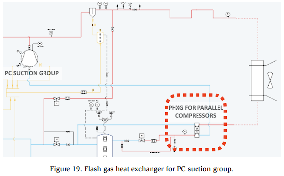
A plate heat exchanger can be employed to mitigate risks associated with these events, which heats the suction gas moving toward the parallel compressors using the CO2 stream exiting the gas cooler (Figure 19).
Conclusions
Appropriate superheat control requirements are crucial when designing transcritical CO2 systems and must be applied to all compressor suction groups, including LR, MT, and PC utilities. This requires a thorough understanding of both the system operating envelope and its load profile.
This paper examined the challenges associated with superheat control in transcritical CO2 systems. On one hand, it is essential to avoid compressor wet operation by maintaining a superheat of at least 18°R (10K); on the other hand, excessive superheat can result in elevated compressor temperatures. For this reason, superheat should be maintained within the limits imposed by the compressor manufacturer.
This paper describes several system architectures that can help maintain compressors’ suction temperature within the desired levels, ensuring compressor longevity and system efficiency.
References
Pisano, G. (2022). Transcritical CO2 compressors: Challenges in Industrial Refrigeration Applications. International Institute of Ammonia Refrigeration (IIAR).
Pisano, G. (2024). CO2 systems add-ons: Calculations and Field Measurements. International Institute of Ammonia Refrigeration (IIAR).
Pisano, G. (2025). CO2 systems: Lubricants & Oil Management Strategies. International Institute of Ammonia Refrigeration (IIAR).
Shecco. (2024). Market trends. Atmo US.
Officine Mario Dorin S.p.A. (n.d.-a). Operating instructions for CO2 compressors. https://dorin.com/documents/Download/2/1LTG665-14.pdf
Officine Mario Dorin S.p.A. (n.d.-b). Dorin software 25.03. selection.dorin.com